Testing clamp for testing tensile stress-tensile strain of metal bar samples

A tensile stress and tensile strain technology, applied in the direction of measuring devices, analytical materials, instruments, etc., can solve the problems of large amount of blanks, insufficiency, high price, etc., to save testing costs, easy installation, and alignment. good effect

Inactive Publication Date: 2012-09-19
TECHNICAL INST OF PHYSICS & CHEMISTRY - CHINESE ACAD OF SCI
View PDF5 Cites 12 Cited by
  • Summary
  • Abstract
  • Description
  • Claims
  • Application Information

AI Technical Summary

Problems solved by technology

However, sometimes due to the constraints of the following reasons, the low-temperature mechanical tensile stress-tensile strain performance test of some metal materials cannot be effectively carried out
[0003] 1. At present, most of the tensile stress-tensile strain performance tests of metal materials at low temperatures are tested in accordance with national standards using relatively large dumbbell-shaped samples. In view of the significant increase in tensile strength of many metal materials at ultra-low temperatures, In a low temperature environment, the load on a relatively large dumbbell-shaped metal sample exceeds the bearing capacity of the low temperature test part itself, and the test cannot be carried out effe

Method used


Image

  • Testing clamp for testing tensile stress-tensile strain of metal bar samples
  • Testing clamp for testing tensile stress-tensile strain of metal bar samples
  • Testing clamp for testing tensile stress-tensile strain of metal bar samples

Examples


Embodiment Construction

[0032] The present invention will be further described below in conjunction with the accompanying drawings and embodiments.

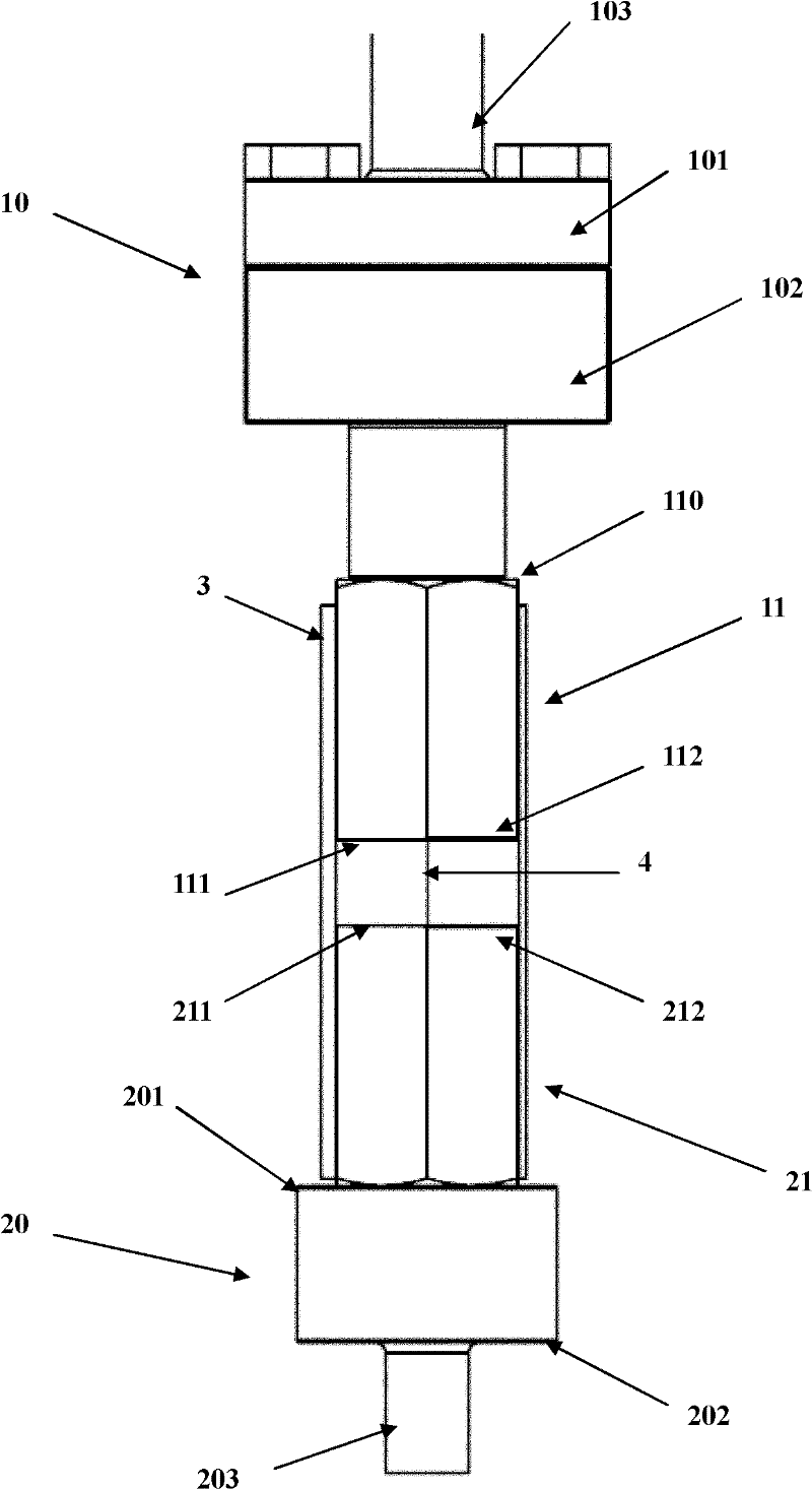
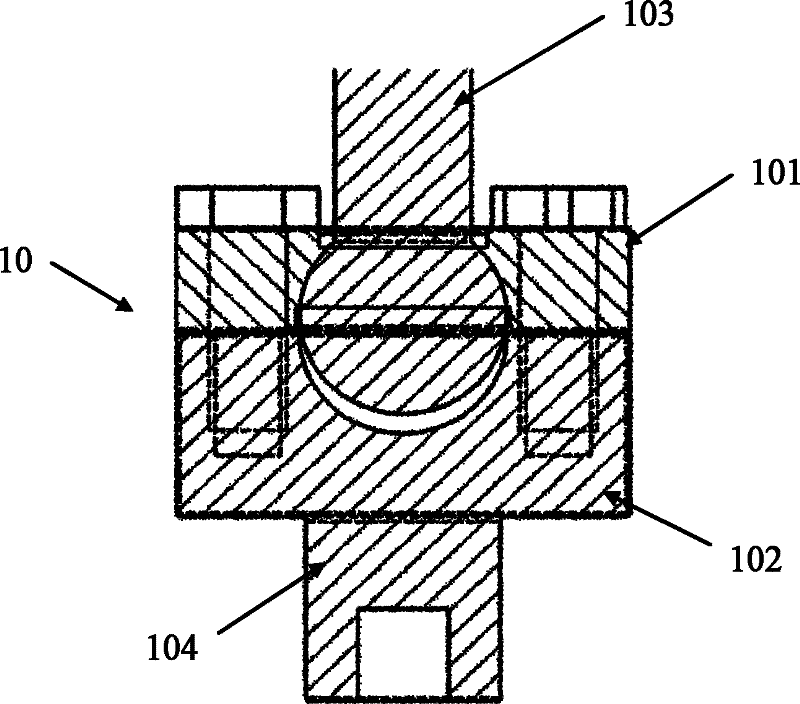
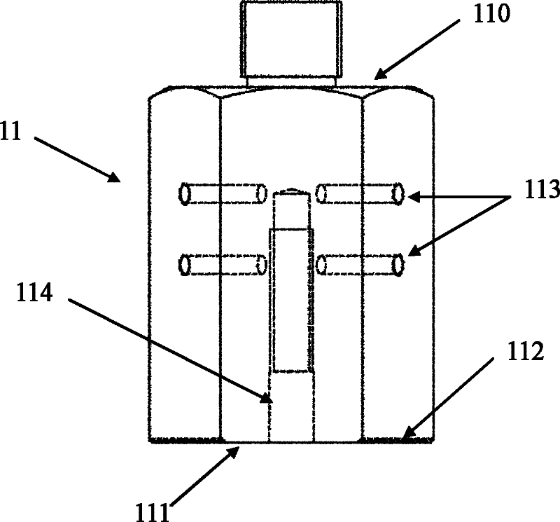
[0033] figure 1 It is a structural schematic diagram of the present invention; figure 2 It is a schematic structural view of the upper connection part 10; image 3 It is a structural schematic diagram of the upper chuck 11; Figure 4 It is a structural schematic diagram of the lower chuck 21; Figure 5 It is a schematic structural diagram of the lower connection tooling 20; Image 6 It is a schematic diagram of the assembly of the upper chuck 11, the lower chuck 21 and the guide baffle 3; Figure 7 It is a schematic diagram of the upper horizontal knife-edge groove 112 and the lower horizontal knife-edge groove 212 . As can be seen from the figure, the test fixture for testing the tensile stress-tensile strain of the metal bar sample provided by the present invention consists of an upper connection part 10, an upper clamp 11, a lower clamp 21, a l...


PUM


Abstract

The invention relates to a testing clamp for testing tensile stress-tensile strain of a metal bar samples. The clamp comprises an upper connecting part, a lower connecting part, an upper clamping head, a lower clamping head and a guiding baffle plate fixing member, wherein a drag link ball of the upper connecting part is disposed in a shrinkage pool which is formed by a pressure flange and an upper connecting workpiece; the upper clamping head and the lower clamping head are equilateral polyhedra which are in the same shape and in a vertical arrangement, are separated by a distance of 1-3 cm, and are respectively provided with horizontal knife-edge grooves on opposite surfaces; the upper clamping head is threadedly connected with the upper connecting part, and the lower clamping head is threadedly connected with the lower connecting part; the guiding baffle plate fixing member coats three adjacent side surfaces of the upper clamping head and the lower clamping head which are opposite placed, has three vertical baffle plates, is fixed with the upper clamping head, and positions and guides the upper clamping head and the lower clamping head; and a middle vertical baffle plate is fixed with a side surface of the upper clamping head, wherein the side surface is provided with a first horizontal screw hole. The testing clamp has characteristics of easy installation and accurate position, and can achieve tensile stress-tensile strain mechanical performance tests for standard or non-standard metal bar samples under a low temperature environment with a temperature ranging form the room temperature to 4.2 K.

Description

technical field [0001] The invention relates to a test fixture, in particular to a test fixture for testing the tensile stress-tensile strain mechanical properties of a metal bar sample at room temperature to 4.2K. Background technique [0002] At present, with the continuous emergence of metal alloy materials, especially the wide application of some rare metal materials in national defense, aerospace and civil fields, it is particularly urgent to obtain low-temperature mechanical properties of materials, especially ultra-low temperature (77K to 4.2K) mechanical properties. . The tensile mechanical properties of metal materials under ultra-low temperature conditions are also one of the main concerns of national defense and aerospace. But sometimes due to the constraints of the following reasons, the low-temperature mechanical tensile stress-tensile strain performance test of some metal materials cannot be effectively carried out. [0003] 1. At present, most of the tensile...

Claims


Application Information

Patent Timeline
IPC IPC(8): G01N3/04
Inventor 渠成兵付绍云肖红梅杨姣萍冯青平
Owner TECHNICAL INST OF PHYSICS & CHEMISTRY - CHINESE ACAD OF SCI
Why Eureka
Try Eureka