Measurement apparatus and measurement method

A technology of measuring device and area, which is applied in the direction of measuring device, instrument, material analysis by optical means, etc., can solve the problem of inability to perform measurement, and achieve the effect of improving detection sensitivity and suppressing structural complexity.

Inactive Publication Date: 2012-09-19
SEIKO EPSON CORP
View PDF6 Cites 2 Cited by
  • Summary
  • Abstract
  • Description
  • Claims
  • Application Information

AI Technical Summary

Problems solved by technology

In this way, since the intensity of the detected Raman scattered light is not proportional to the concentration of the substance, there is a problem that quantitative analysis for measuring the concentration of the substance cannot be performed even if only the intensity of the Raman scattered light is obtained.

Method used


Image

  • Measurement apparatus and measurement method
  • Measurement apparatus and measurement method
  • Measurement apparatus and measurement method

Examples


no. 1 approach

[0062] Next, a first embodiment of the present invention will be described with reference to the drawings.

[0063] [Overall structure of the measurement device]

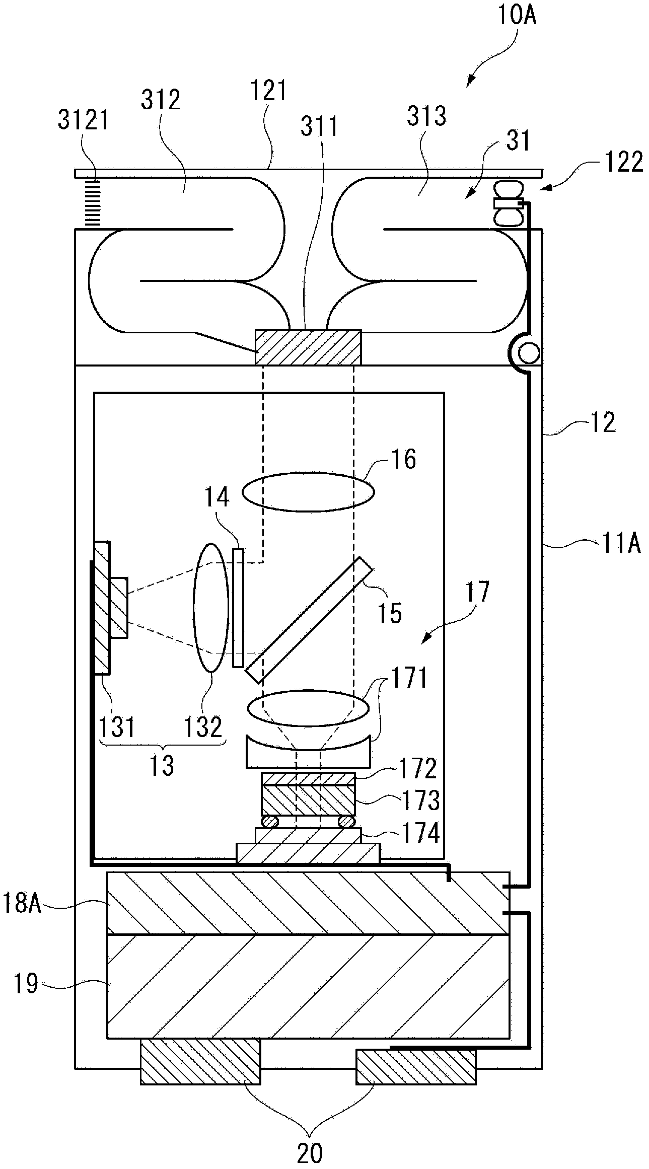
[0064] figure 1 It is a schematic diagram showing the configuration of a measurement device 10A according to the first embodiment of the present invention.

[0065] The measurement device 10A according to the present embodiment is a measurement device that measures the concentration of the target substance while identifying the target substance included in the sample. Such as figure 1 As shown, this measurement device 10A is configured to include a device main body 11A and an exchange unit 31 that is interchangeably attached to the device main body 11A.

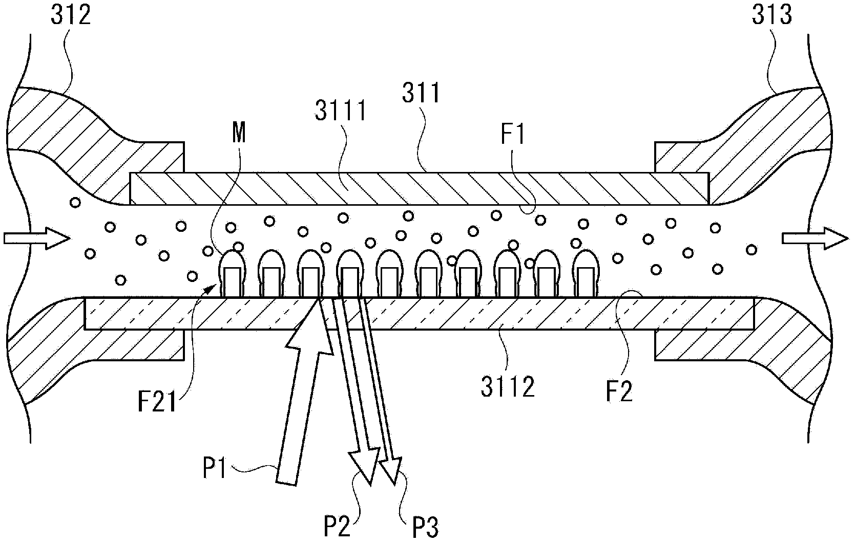
[0066] Among them, the exchange unit 31 forms a channel through which the sample flows. A sensor chip 311 is provided in the flow channel, and the device main body 11A irradiates light (laser light) to the sensor chip 311 to detect Raman scattered light emitted...

no. 2 approach

[0120] Next, a second embodiment of the present invention will be described.

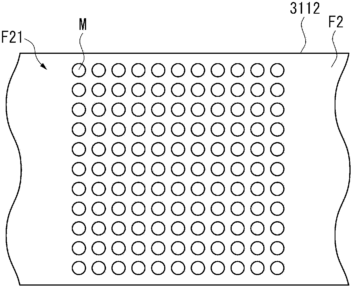
[0121] The measurement device according to this embodiment has the same configuration as the measurement device 10A described above. Here, in the measuring device 10A, the concentration corresponding to the number of regions where enhanced Raman scattered light is detected on the sample contact surface F2 is acquired from the LUT of the storage unit 185A. On the other hand, in the measuring device according to the present embodiment, the sum of the intensities of Raman scattered light received from each area is calculated, and the concentration corresponding to the sum is acquired from the storage unit. In this point, the measurement device according to the present embodiment is different from the measurement device 10A. In addition, in the following description, the same code|symbol is attached|subjected to the part which is the same or substantially the same as what has already been demonstrated,...

no. 3 approach

[0139] Next, a third embodiment of the present invention will be described.

[0140] The measurement device according to this embodiment has the same configuration as the measurement devices 10A and 10B described above. Here, the measurement device 10A separates the light emitted from the light source device 13 into a plurality of partial beams, and measures the target light intensity based on the intensity of Raman scattered light received from each region irradiated with each partial beam on the sample contact surface F2. concentration of the substance. In contrast, in the measurement device according to this embodiment, the position of the light-incident region on the sample contact surface F2 is changed, and the Raman scattered light is received for each region to measure the concentration of the target substance. In this point, the measurement device according to the present embodiment is different from the measurement devices 10A and 10B described above. In addition, i...


PUM

PropertyMeasurementUnit
sizeaaaaaaaaaa
diameteraaaaaaaaaa

Abstract

The invention provides a measurement apparatus and a measurement method. The measurement apparatus for measuring the concentration of a target substance contained in a sample includes: a light source (light source device); a light-incident body (sensor chip) that has a sample contact surface, where an enhanced electric field is formed by metal particles, and enhances Raman scattering light radiated from the target substance by light emitted from the light source in the enhanced electric field; an irradiation unit that causes the light emitted from the light source to enter into a plurality of areas in the light-incident body; a light-receiving unit (light-receiving element) that receives the Raman scattering light radiated from a plurality of the areas; and a quantitative measurement unit (control device) that quantitatively measures a concentration of the target substance based on a total number of the areas and a strength of the Raman scattering light received from the areas.

Description

technical field [0001] The present invention relates to a measuring device and a measuring method. In particular, it relates to a measurement device and a measurement method for detecting Raman scattered light generated by incident light on a target substance included in a sample, and measuring the concentration of the target substance in the sample. Background technique [0002] Conventionally, there is known a Raman spectroscopy apparatus that irradiates a sample with light and identifies the substance based on a fingerprint spectrum obtained from Raman scattered light emitted from a substance included in the sample. However, since such Raman scattered light is weak, the fingerprint spectrum may not be obtained reliably in some cases. [0003] To address such a problem, there is known a Raman spectroscopy device (handheld Raman device) (for example, see Patent Document 1) that forms an enhanced electric field to enhance Raman scattered light and receives the enhanced Rama...

Claims


Application Information

Patent Timeline
Patent Type & Authority Applications(China)
IPC IPC(8): G01N21/65
CPCG01N21/658
Inventor 桥元伸晃
Owner SEIKO EPSON CORP
Why Eureka
Try Eureka