

Dipole array acoustic logging instrument
A sonic logging tool and logging tool technology, applied in the field of exploration technology and equipment, can solve the problems of high logging cost, unlaunched tools, and difficulty in promoting the application of tool logging
- Summary
- Abstract
- Description
- Claims
- Application Information
AI Technical Summary
Problems solved by technology
Method used
Image

Examples
Embodiment Construction
[0030] The technical solutions of the present invention will be described in detail below in conjunction with the accompanying drawings.
[0031] The theoretical basis of dipole acoustic logging to measure the formation shear wave velocity is that the flexural wave in the borehole acoustic field has a wave velocity close to that of the formation shear wave when the frequency is low enough (the frequency in the borehole is about 1k-4kHz). Therefore, dipole acoustic logging uses a dipole acoustic source to excite low-frequency borehole flexural waves (bending mode), and the shear wave velocity is obtained by measuring the velocity of the flexural waves.
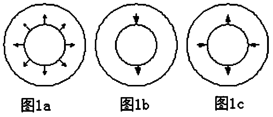
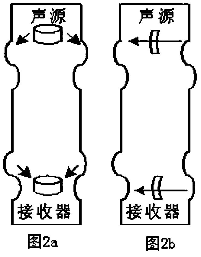
[0032] Dipole acoustic logging uses dipole transmitting transducers to excite bending modes in the wellsite. figure 1 Generates the direction of pressure waves for monopole, dipole, and quadrupole sources. figure 2 In the figure, a is the wave mode produced by conventional acoustic logging tools, and b is the bending wave mod...
PUM
 Abstract
Description
Claims
Application Information