Device for detecting defect on surface of steel billet

A billet and defect technology, applied in the field of testing equipment, can solve the problems of not very objective judgment of billet quality, manual observation, unfavorable surface conditions, etc., achieve good social and economic prospects, avoid deep processing, and have excellent performance

Inactive Publication Date: 2012-09-19
WEIER AUTOMATION CO LTD TANGSHAN IRON & STEELGRP
View PDF6 Cites 0 Cited by
  • Summary
  • Abstract
  • Description
  • Claims
  • Application Information

AI Technical Summary

Problems solved by technology

Traditional detection methods generally require manual observation, and there are usually three methods: the first is to observe the steel billet at close range to determine the defective steel billet. Since the temperature of the steel billet at this time is about 1000 degrees Celsius, close observation is extremely dangerous; The second method is to observe the surface defects after the steel billet is cooled, but due to production needs, the steel billet will pass through the heating furnace and rolling mill after the minimum temperature loss, so as to meet the full utilization of energy and environmental protection requirements. Allowed; the third method is to indirectly observe the surface condition of the steel billet by the operator through the camera device, but this method has a limited observation field of view for the steel billet, which is not conducive to a comprehensive grasp of its surface condition
All of the above methods have visual fatigue due to long-term and large-scale observation by operators, and there are factors that are not very objective in judging the quality of steel billets, which not only leads to low recognition efficiency, but also easily leads to hidden dangers of missed detection

Method used


Image

  • Device for detecting defect on surface of steel billet
  • Device for detecting defect on surface of steel billet
  • Device for detecting defect on surface of steel billet

Examples


Embodiment Construction

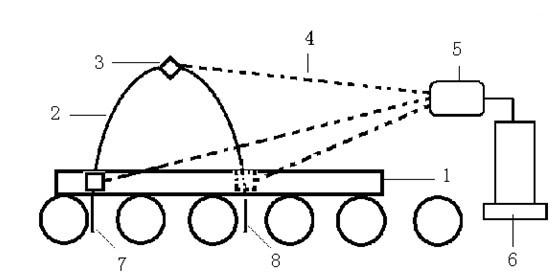
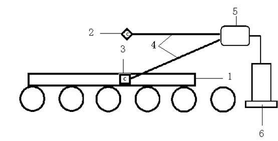
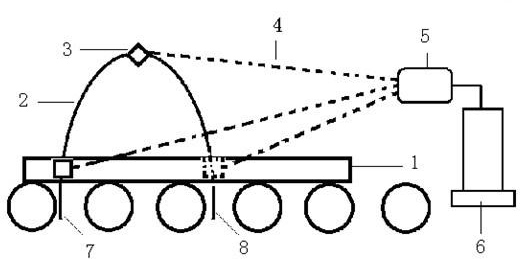
[0010] The invention is a machine vision-based object surface defect detection device through imaging-analysis-result-operation, which consists of a fixing device, a collection device, a processing device and a control device. The fixing device is a sliding track 2 , the acquisition device is an industrial camera 3 or a related image acquisition device, and the processing device includes an industrial computer 6 and a PLC cabinet 5 .

[0011] The PLC cabinet 5 is connected to the industrial camera 3 and the industrial computer 6 respectively, and the operation monitoring HMI of the industrial computer 6 includes hardware and screen writing software.

[0012] The industrial computer 6 is carried out according to the edited logic algorithm. The algorithm includes the recognition algorithm for the upper surface of the billet and the recognition algorithm for the two sides of the billet according to the different detection positions. According to the recognition steps, it is divide...


PUM


Abstract

The invention discloses a device for detecting a defect on the surface of a steel billet, which belongs to the technical field of detection equipment and is used for detecting the defect on the surface of the steep billet. The technical scheme is that: the device consists of a sliding track, an industrial camera, a programmable logic controller (PLC) cabinet, and an industrial personal computer, wherein the sliding track is arranged above a conveying roller of the steel billet; the industrial camera is arranged above the sliding track; and the signal output end of the industrial camera is connected with the PLC cabinet which is connected with an operation monitoring human machine interface (HMI) of the industrial personal computer by a communication card. According to the device, data is acquired by the industrial camera and is intelligently analyzed by a program, and then is directly displayed by the operation monitoring HMI of the industrial personal computer and is intuitively displayed to a site operator in real time, so that the further processing for a semi-finished product with defects is avoided. The device has the advantages of real-time performance, simplicity and convenience, high efficiency and objectivity, and can be further applied to the surface detection of other high-temperature, poisonous and harmful large objects and the like, thereby having excellent social and economic prospects.

Description

technical field [0001] The invention relates to a device for detecting surface defects of steel slabs, belonging to the technical field of detection equipment. Background technique [0002] In modern industrial production, the billets or ingots produced by continuous casting machines may have defects such as deep scratches, surface defects, and unsatisfactory narrow-side rectangular coefficients. Therefore, after the billets are produced, they need to be inspected. Inspection, in order to eliminate defective products, avoid deep processing of defective semi-finished products, and reduce waste of manpower and material resources. Traditional detection methods generally require manual observation, and there are usually three methods: the first is to observe the steel billet at close range to determine the defective steel billet. Since the temperature of the steel billet at this time is about 1000 degrees Celsius, close observation is extremely dangerous; The second method is t...

Claims


Application Information

Patent Timeline
Patent Type & Authority Applications(China)
IPC IPC(8): G01N21/896
Inventor 王泽生万海龙高爱国秦久莲李辉宋鸿斌刘春伶周姗姗张立红
Owner WEIER AUTOMATION CO LTD TANGSHAN IRON & STEELGRP
Why Eureka
Try Eureka