Eureka AIR delivers breakthrough ideas for toughest innovation challenges, trusted by R&D personnel around the world.

Electronically controlled fluid gas density stabilizing device for spectrograph

An electronic control and gas density technology, which is applied in the field of detection and analysis of spectrometers, can solve the problems of high machining accuracy, difficult debugging, and difficult control accuracy, achieving high-precision density control and improving measurement stability.

Inactive Publication Date: 2012-09-19
SHENZHEN UNIQUE METRICAL TECH
View PDF5 Cites 5 Cited by
  • Summary
  • Abstract
  • Description
  • Claims
  • Application Information

AI Technical Summary

Problems solved by technology

The first method requires high machining precision, difficult to master the control accuracy, and difficult to debug; the second method uses an electronically controlled micro-flow valve to control the gas supply, and the pressure control accuracy can be very high, but requires constant temperature. Very high temperature stability, once the temperature fluctuates or changes, it will inevitably cause fluctuations in the working gas density
Especially in the start-up stage after the instrument is shut down, it takes a period of time to wait for the constant temperature room to completely reach the temperature equilibrium. During this period of time, the air flow density is incorrect, resulting in a large deviation of the spectral peak position of the ray.
Or if the temperature control target in the constant temperature room is modified, the peak position will also deviate greatly, which is very unfavorable for X-ray intensity detection

Method used


Image

  • Electronically controlled fluid gas density stabilizing device for spectrograph
  • Electronically controlled fluid gas density stabilizing device for spectrograph
  • Electronically controlled fluid gas density stabilizing device for spectrograph

Examples


Embodiment Construction

[0016] The present invention will be further described below in conjunction with specific examples, but the present invention is not limited to the following examples.

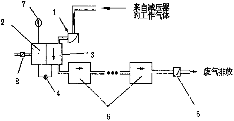
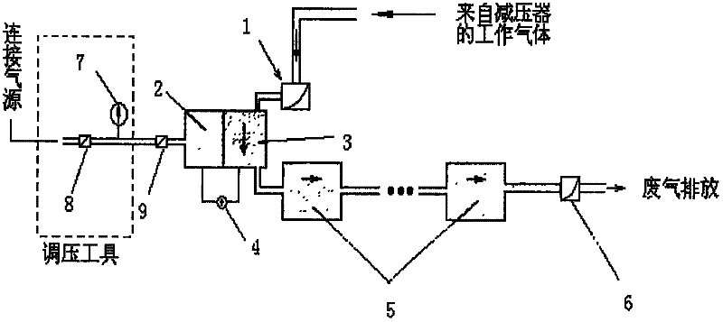
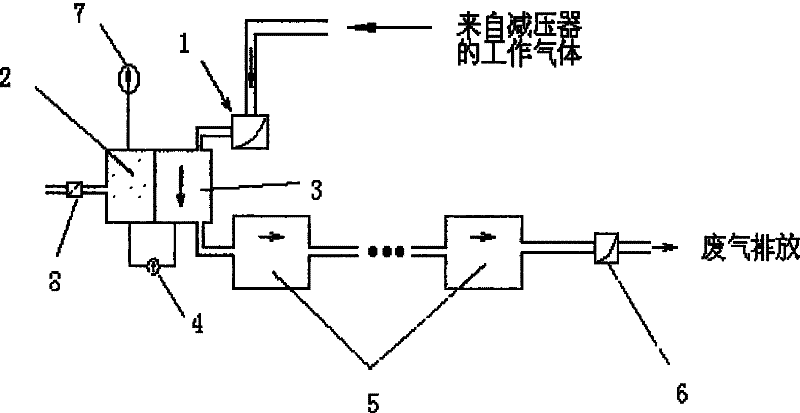
[0017] Such as figure 1 It is the flow chart of adjusting the preset pressure of the airtight chamber of the present invention; the working gas from the pressure reducer enters the flow chamber 3 through the micro-flow proportional control valve 1, and the gas micro-pressure difference sensor 4 is connected between the flow chamber 3 and the airtight chamber 2 , the airtight chamber 2 is pre-filled with the working gas higher than the working pressure through the regulating valve 8, the gas pressure is monitored by the absolute pressure sensor 7, and then the proper working pressure is achieved by adjusting a small amount of deflation with the regulating valve 8, which may need to be repeated The proper pressure can only be reached by degassing again, and finally the regulating valve 8 is closed. The flow cav...


PUM


Abstract

The invention discloses an electronically controlled fluid gas density stabilizing device for a spectrograph. An airtight cavity is served as a reference cavity; a working gas is filled into the airtight cavity in advance; the gas pressure of the airtight cavity is monitored by a pressure sensor connected with the airtight cavity; the pressure of the airtight cavity is adjusted to be a required value by continuously filling or slightly releasing gas; a micro-flow proportional control valve is used for controlling gas flow of the working gas inputted into a flowing cavity; the releasing volume of the gas in the flowing cavity is controlled by the micro-flow proportional control valve; a pressure difference of the airtight cavity and the flowing cavity is detected by a micro-pressure difference sensor; and under the condition of same temperature of the flowing cavity and the airtight cavity, the gas pressure of the flowing cavity and the gas pressure of the airtight cavity are maintained as 0 or preset value, by adjusting the micro-flow proportional control valve for replenishing gas into the flowing cavity and the micro-flow proportional control valve for controlling the discharging of the gas in the flowing cavity, so that the purpose of stabilizing the density of the gas in the flowing cavity is achieved.

Description

technical field [0001] The invention belongs to the detection and analysis field of a spectrometer, in particular to an electronically controlled flow gas density stabilization device for a spectrometer. Background technique [0002] The X-ray fluorescence spectrometer is mainly composed of excitation, dispersion, detection, recording and data processing units. The role of the excitation unit is to generate primary X-rays. It consists of a high voltage generator and an X-ray tube. The latter are more powerful and are cooled with water and / or oil. The role of the dispersion unit is to monochromatize the characteristic fluorescent X-rays of the elements to be measured. It is composed of sample chamber, slit, goniometer, analysis crystal and other parts. By rotating the analytical crystal and the detector at a speed of 1:2 with the goniometer, X-rays of different wavelengths can be measured at different Bragg angle positions for qualitative analysis of elements. The functi...

Claims


Application Information

Patent Timeline
Patent Type & Authority Applications(China)
IPC IPC(8): G01T7/00
Inventor 刘小东
Owner SHENZHEN UNIQUE METRICAL TECH
Why Eureka
Eureka Blog
Learn More