Front vehicle detection method based on monocular vision
A technology of the vehicle ahead and detection method, applied in the field of intelligent vehicle assisted driving system, can solve the problems that the vehicle model is difficult to take into account all models, the model matching algorithm has a large amount of calculation, and the real-time performance of the detection method is reduced, so as to achieve high reliability and improve Robustness and good real-time effect
- Summary
- Abstract
- Description
- Claims
- Application Information
AI Technical Summary
Problems solved by technology
Method used
Image

Examples
Embodiment Construction
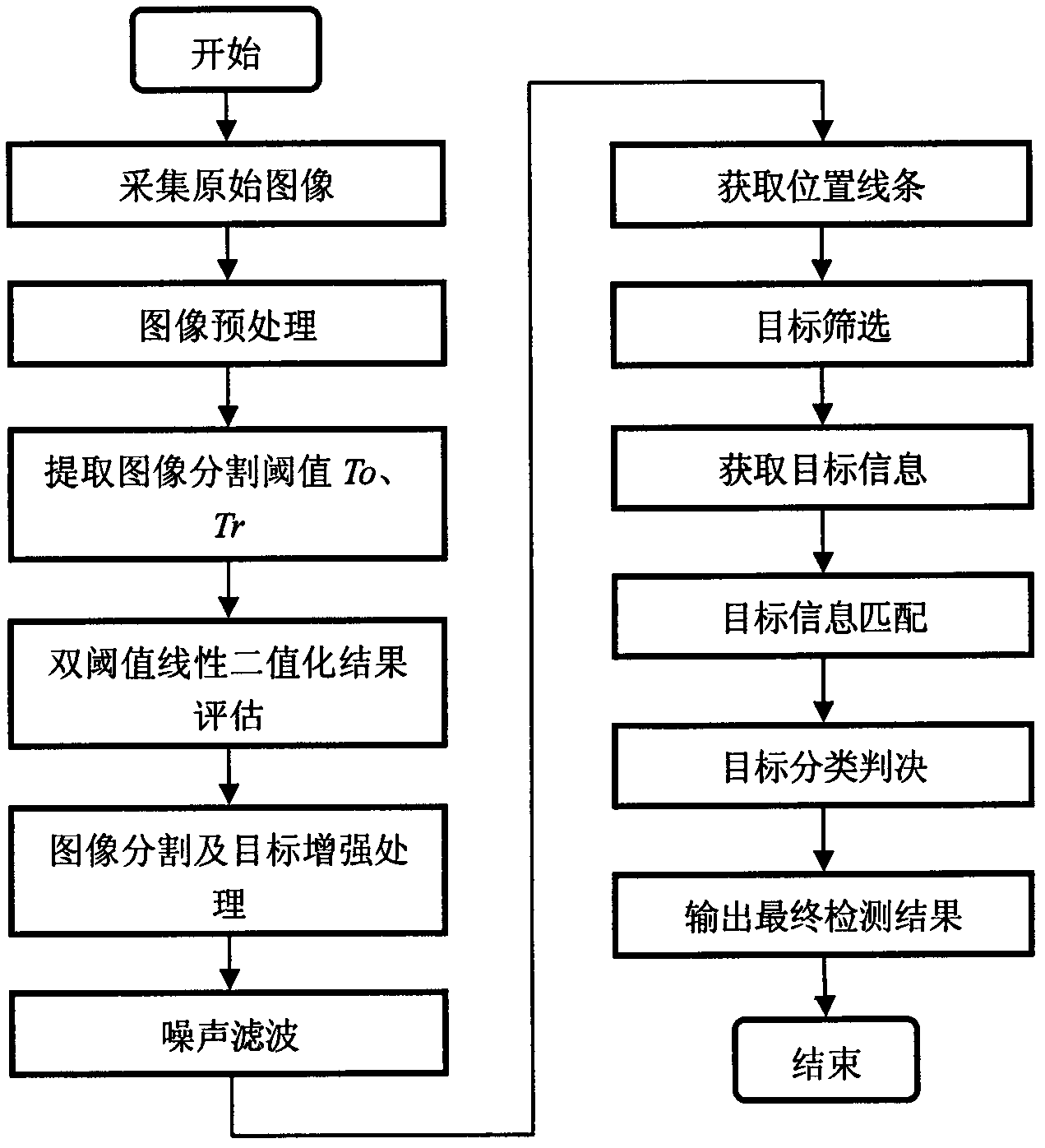
[0057] The general flow chart of the vehicle detection method based on monocular vision in the present invention is as follows figure 1 As shown, firstly, the grayscale image of the road ahead of the vehicle is preprocessed, and the bottom shadow of the vehicle is segmented from it, and then the false vehicle is filtered out through the position and geometric characteristics of the bottom shadow of the vehicle, and finally, the unstable target is filtered out through the target tracking judgment, and the obtained Final vehicle inspection results. The implementation process of the present invention will be described in further detail below in conjunction with the accompanying drawings.
[0058] 1. Image acquisition and preprocessing
[0059] (1) Raw image acquisition
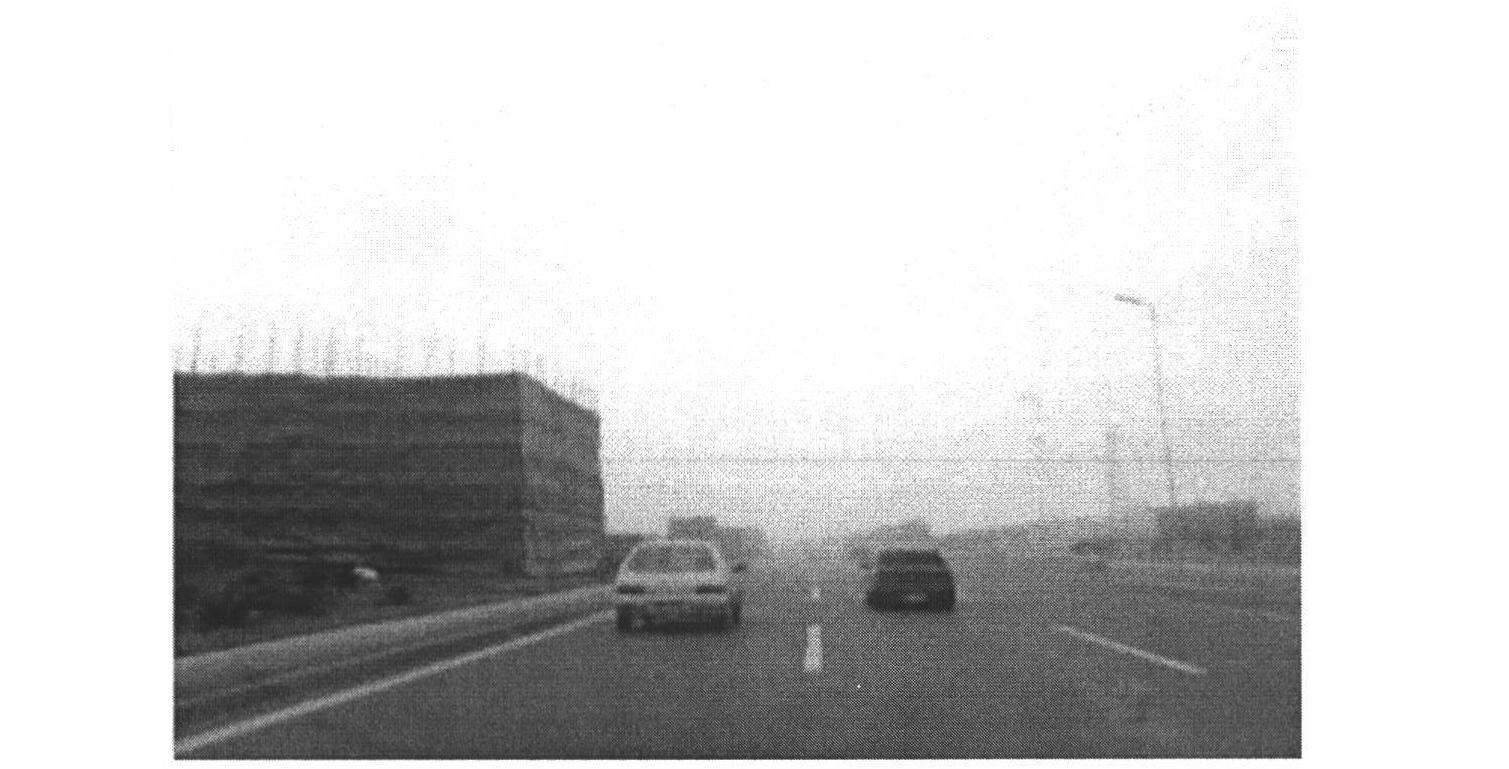
[0060] Use a CMOS black and white industrial camera to collect grayscale images in real time. Set the parameters of the industrial camera so that the frame rate of the captured video reaches 25 frames / s, and t...
PUM
 Abstract
Description
Claims
Application Information