Supercharge Your Innovation With Domain-Expert AI Agents!

Die bonder

A technology of bonding crystals and grains, which is applied in the manufacture of conveyor objects, electrical components, semiconductors/solid-state devices, etc., can solve problems that affect the overall process time and efficiency, do not meet production requirements, and long operating hours, etc., to shorten the operation Time, good precision, and faster production speed

Active Publication Date: 2016-09-21
GALLANT MICRO MACHINING
View PDF6 Cites 0 Cited by
  • Summary
  • Abstract
  • Description
  • Claims
  • Application Information

AI Technical Summary

Problems solved by technology

[0006] First of all, the die bonding machine is a relatively new technology for each manufacturer, so each manufacturer only slightly modifies the old equipment, so it is easy to cause poor accuracy
[0007] In addition, the swing arm type pick-and-place device needs to move the swing arm between the grain platform and the wafer platform, so the length of the swing arm is relatively long, so its accuracy is not good. If the swing arm operates too fast, The inertial effect of the swing arm will cause the die to drop. If the speed of the swing arm is reduced to facilitate control, it will not cause the die to fall, but it will seriously affect the time and efficiency of the overall process.
[0008] Furthermore, manually loading and unloading the wafer carrier requires a long working time, so it does not meet the production requirements
[0009] Based on the above, the existing die bonding machines have the disadvantages of poor precision, grain drop and inconsistent production requirements

Method used


Image

  • Die bonder
  • Die bonder
  • Die bonder

Examples


Embodiment Construction

[0051] Specific embodiments of the present invention are described below with specific examples, and those skilled in the art can easily understand other advantages and effects of the present invention from the content disclosed in this specification.

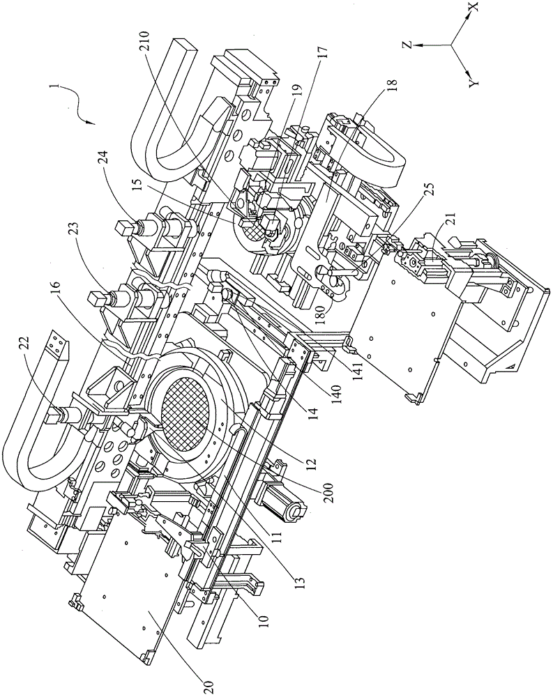
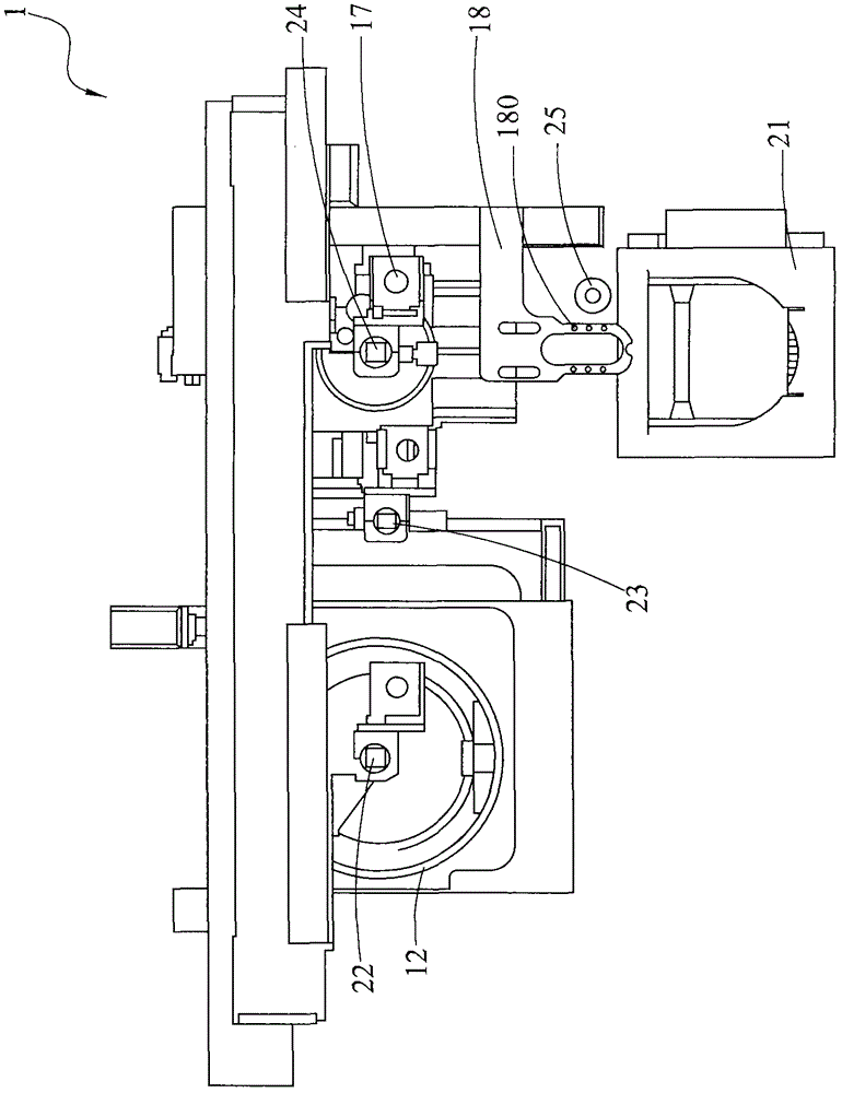
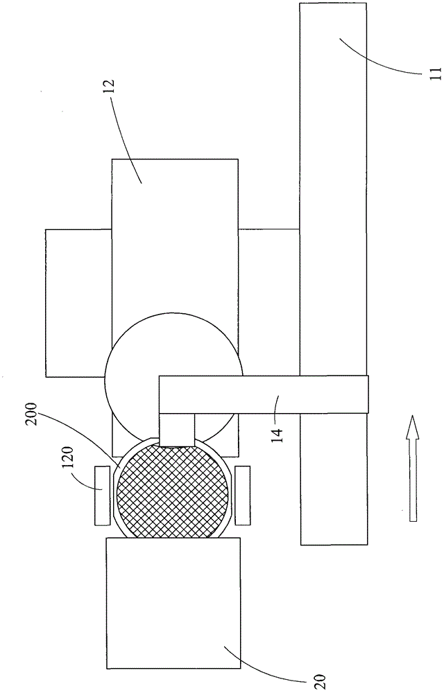
[0052] Please cooperate with reference figure 1 and figure 2 As shown, the present invention is a die bonding machine, which has a machine platform 1, a die ring moving device 10, a first slide rail 11, a die ring carrying device 12, a first pick-and-place device 13, A grain positioning device 14, a substrate carrying device 15, a second slide rail group 16, a dispensing module 17, a substrate moving device 18, a second pick-and-place device 19, a grain basket lifting device 20, a crystal The boat box lifting device 21 , a first vision module 22 , a second vision module 23 , a third vision module 24 , and a substrate positioning device 25 .

[0053] The machine 1 has an X axis, a Y axis and a Z axis.

[0054] The die ring c...


PUM


Abstract

The present invention provides a die bonder characterized in that: a die ring bearing device, a first pick-and-place device, a die positioning device, a second pick-and-place device, a substrate bearing device, a first visual module, a second visual module, and a third visual module are arranged in a machine; wherein, the first pick-and-place device and the second pick-and-place device move the die in a staged way, and the third visual module performs optical alignment, so that the die can be accurately bonded to a substrate, thereby achieving the effects of shortening manual processing time, satisfying production requirements, avoiding drop of the die, and having a better accuracy.

Description

technical field [0001] The invention relates to a die bonding machine, which provides a mechanical segmental movement of the die and alignment of the vision module, which can accurately and avoid the fall of the die, so that the die can be pasted on the At the substrate, the substrate with the crystal grains is moved mechanically, so as to meet the production requirements, avoid the crystal grains from falling, and achieve better precision. Background technique [0002] Existing die bonding machine, it has a machine platform, is provided with a grain (Die) platform and a wafer (Wafer) platform in the machine platform, and is provided with a swinging arm type pick-up between the crystal platform and the wafer platform. put the device. [0003] In actual operation, the staff manually place the carrier carrying a plurality of dies on the die platform, and place the carrier plate with the wafer on the wafer platform. [0004] The pick-and-place device takes out the die from th...

Claims


Application Information

Patent Timeline
Patent Type & Authority Patents(China)
IPC IPC(8): H01L21/58H01L21/677H01L21/68
Inventor 石敦智刘建志林语尚谢铭良
Owner GALLANT MICRO MACHINING
Features
  • R&D
  • Intellectual Property
  • Life Sciences
  • Materials
  • Tech Scout
  • Unparalleled Data Quality
  • Higher Quality Content
  • 60% Fewer Hallucinations
Learn More