Substrate clamping device

A technology of substrate clips and substrates, which is applied in the manufacture of electrical components, semiconductor/solid-state devices, circuits, etc., can solve the problems of complex transmission structure of the manipulator, large loss of transmission energy-consuming parts, and increase the difficulty of manipulator manufacturing, etc., to achieve a compact structure , Transmission energy consumption and component loss are less, easy to install and flexible

Pending Publication Date: 2012-09-19
DONGGUAN ANWELL DIGITAL MASCH CO LTD
View PDF3 Cites 9 Cited by
  • Summary
  • Abstract
  • Description
  • Claims
  • Application Information

AI Technical Summary

Problems solved by technology

[0004] However, the transmission structure of the manipulator is very complicated, and the more transmission methods, in order to ensure the transmission accuracy and strength, correspondingly, higher strength and precision requirements are put forward for the various components that make up the manipulator. On the one hand, the manipulator increases. It is difficult to manufacture, which increases the manufacturing cost accordingly. On the other hand, the energy consumption of the transmission and the loss of components are large, and the maintenance is inconvenient.

Method used


Image

  • Substrate clamping device
  • Substrate clamping device
  • Substrate clamping device

Examples


Embodiment Construction

[0018] In order to describe the technical content and structural features of the present invention in detail, further description will be given below in conjunction with the implementation and accompanying drawings.

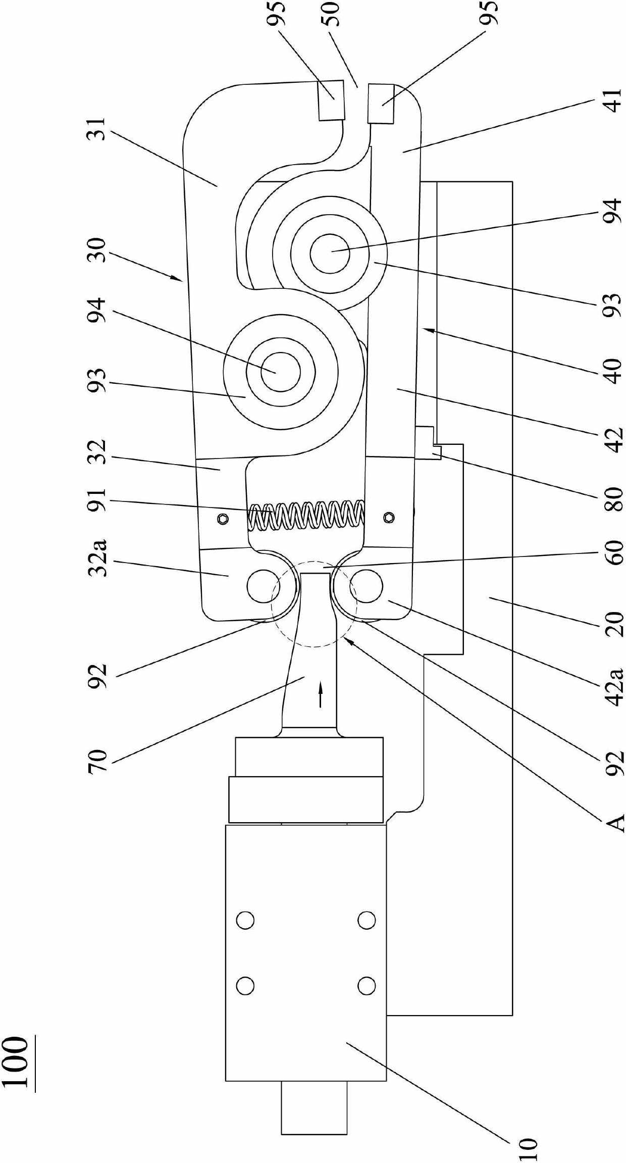
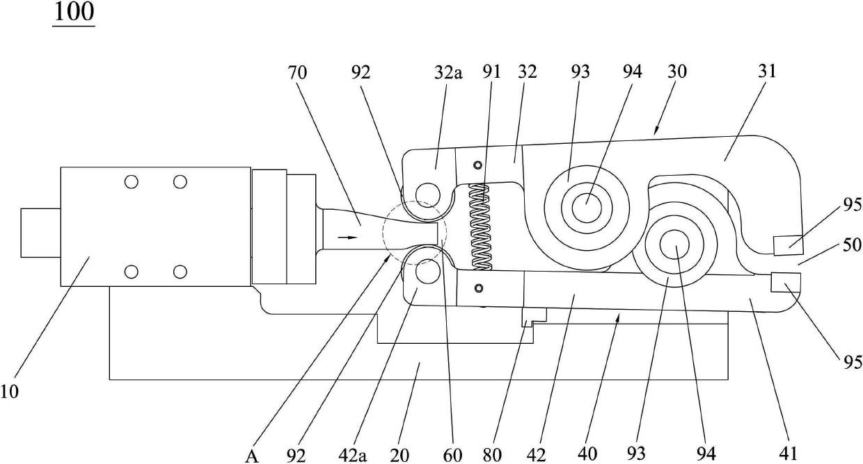
[0019] see figure 1 and figure 2 , the substrate clamping device 100 of the present invention is used for clamping substrates in organic light-emitting displays and solar panels, wherein the substrate clamping device 100 includes a driver 10, a bottom plate 20 and a first clamp that cooperates with each other Fastener 30 and second clamping piece 40. Both the first and second clamping parts 30, 40 are pivotally connected to one end of the bottom plate 20, and the first and second clamping parts 30, 40 each have clamping parts 31, 41 and a pushing part 32 , 42; Specifically, in this embodiment, the first and second clamping members 30, 40 are pivotally connected to the bottom plate 20 in such a way that the substrate clamping device 100 of the present invention...


PUM


Abstract

The invention discloses a substrate clamping device for clamping substrates in an organic light-emitting display and a solar cell panel. The substrate clamping device comprises a driver, a bottom plate, a first clamping piece and a second clamping piece, wherein the first clamping piece and the second clamping piece are matched with each other. Both the first clamping piece and the second clamping piece are pivoted at one end of the bottom plate and are provided with clamping parts and pushing parts; a clamping region is formed between the clamping parts of the first clamping piece and the second clamping piece; a pushing region is formed between the pushing parts of the first clamping piece and the second clamping piece; the driver is arranged at the other end of the bottom plate; the output end of the driver is provided with a pushing piece corresponding to the pushing region; the driver drives the pushing piece to stretch into the pushing region to eject the pushing parts to rotate along an expanding direction; and the rotating pushing parts drive the clamping parts to rotate along a direction of reducing the clamping region so as to clamp the substrate in the clamping region. The substrate clamping device can overcome the disadvantages of the conventional manipulator that the manufacturing difficulty is great and the manufacturing cost is high; and the substrate clamping device has the advantages of compact structure, convenience for installation and easiness for maintenance.

Description

technical field [0001] The invention relates to a clamping device for clamping a thin-plate-shaped substrate, in particular to a substrate clamping device for reliably clamping the substrate in an organic light-emitting display and a solar battery panel. Background technique [0002] OLED displays made of OLED (full name in English: Organic Light-Emitting Diode, Chinese name: Organic Light-Emitting Diode) are thin and light (panel thickness is generally less than 2 mm), power-saving (operating voltage is generally 3 volts to 10 volts) and other characteristics, so it has been widely used on the display screen of digital products, and has a large market potential. At present, the application of OLED in the world is focused on flat panel display, because OLED is the only one that can be used in applications. It is a technology comparable to TFT-LCD, and it is the only display technology among all current display technologies that can produce large-size, high-brightness, high-r...

Claims


Application Information

Patent Timeline
Patent Type & Authority Applications(China)
IPC IPC(8): H01L21/683
Inventor 蓝劾覃海杨明生
Owner DONGGUAN ANWELL DIGITAL MASCH CO LTD
Why Eureka
Try Eureka