Horizontal Radiating Antenna

A radiation antenna, horizontal direction technology, applied in the direction of antenna, resonant antenna, antenna grounding device, etc., can solve the problems of hindering electromagnetic wave transmission, power leakage, etc., and achieve the effect of easy connection and improved radiation characteristics

Active Publication Date: 2016-12-14
MURATA MFG CO LTD
View PDF5 Cites 0 Cited by
  • Summary
  • Abstract
  • Description
  • Claims
  • Application Information

AI Technical Summary

Problems solved by technology

However, there is no structure to prevent the transmission of electromagnetic waves inside the dielectric substrate
Therefore, an electromagnetic wave in a parallel plate mode is formed between the ground electrode on the surface side and the ground electrode on the back side, and the electromagnetic wave propagates inside the dielectric substrate, causing a problem of power leakage.

Method used


Image

  • Horizontal Radiating Antenna
  • Horizontal Radiating Antenna
  • Horizontal Radiating Antenna

Examples


Embodiment Construction

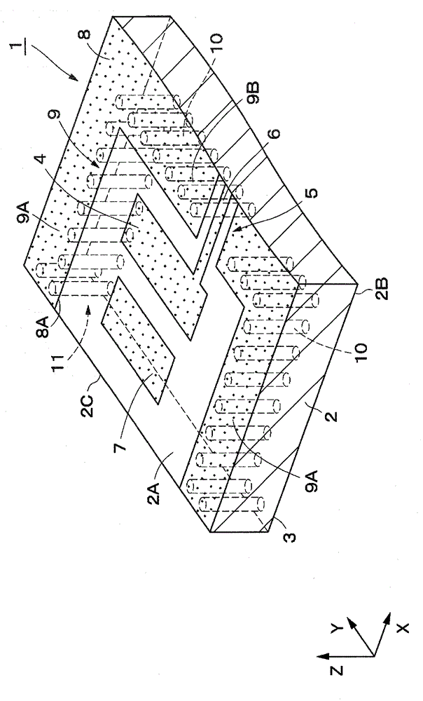
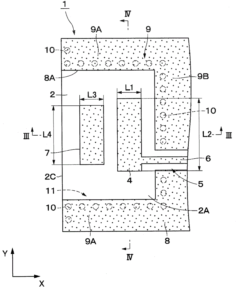
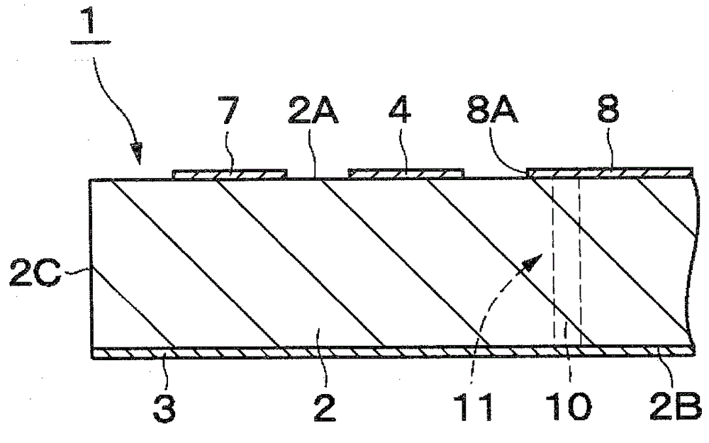
[0052] Hereinafter, as a horizontal radiation antenna according to an embodiment of the present invention, an antenna used in a 60 GHz frequency band will be described in detail with reference to the drawings.

[0053] Figure 1 ~ Figure 4 The horizontal direction radiation antenna 1 of the first embodiment is shown. The horizontal radiation antenna 1 is composed of a substrate 2 , a back side ground conductor plate 3 , a radiation element 4 , a parasitic element 7 , a front side ground conductor plate 8 and the like which will be described later.

[0054] The substrate 2 is formed in a flat plate shape extending parallel to, for example, the X-axis direction and the Y-axis direction among mutually orthogonal X-axis directions, Y-axis directions, and Z-axis directions. The substrate 2 has, for example, a width dimension of about several mm with respect to the Y-axis direction serving as the width direction, has a length dimension of, for example, about several mm with respect...


PUM


Abstract

This disclosure provides a horizontal radiation antenna. The antenna includes a back-surface-side grounded conductor plate on a back surface of a substrate, a radiation element to which a coplanar line is connected on the front surface of the substrate, and a passive element closer to an end portion side of the substrate than the radiation element. A front-surface-side grounded conductor plate is provided at a substantially same height as the radiation element with respect to a thickness direction of the substrate, and a conductive wall surface capable of reflecting a high-frequency signal radiated from the radiation element is provided between the front-surface-side grounded conductor plate and the back-surface-side grounded conductor plate.

Description

technical field [0001] The present invention relates to a horizontal direction radiation antenna suitable for high-frequency signals such as microwaves and millimeter waves. Background technique [0002] As a conventional horizontal radiation antenna, Non-Patent Document 1 describes a structure in which a feeder line, an unbalanced-balun electrode (hereinafter referred to as a balun electrode) are formed on the surface of a dielectric substrate, Radiating elements, passive elements, etc., and a ground conductor plate is formed on the back of the dielectric substrate. [0003] Also, Patent Document 1 describes a structure in which a microstrip line for power feeding and a conductor cover are provided on the surface of a dielectric substrate, and a ground conductor plate is provided on the back surface of the dielectric substrate. In this case, the tip of the microstrip line is located at the end of the dielectric substrate and is electrically connected to the ground conducto...

Claims


Application Information

Patent Timeline
Patent Type & Authority Patents(China)
IPC IPC(8): H01Q1/38H01Q1/48H01Q15/14
CPCH01Q9/0407H01Q1/48H01Q19/005H01Q19/28H01Q21/06
Inventor 须藤薰藤井洋隆小林英一平塚敏朗
Owner MURATA MFG CO LTD
Why Eureka
Try Eureka