Catalytic dewaxing process
A catalytic dewaxing and dewaxing technology, which is used in the recovery of petroleum wax, cracking of hydrocarbon oil, processing of hydrocarbon oil, etc. It can solve the problem that the limited activity of the dewaxing catalyst is difficult to design and can handle all types of feeds.
- Summary
- Abstract
- Description
- Claims
- Application Information
AI Technical Summary
Problems solved by technology
Method used
Image
Examples
Embodiment 1
[0040] The dewaxing catalyst used in this example consisted of 65% by weight ZSM-48 with a 90 / 1 silica to alumina molar ratio and 35% by weight ZSM-48 in the form of a 1.5 mm diameter by 3.25 mm length quadrulobe extrudate. Aluminum composition. This extrudate was steamed at 482° C. for 3 hours and then impregnated with 0.3% by weight platinum (in the form of tetraammine platinum nitrate salt). The catalyst was loaded into a vertical downflow reactor below the top layer of hydrotreating catalyst comprising 15 wt% Pt / Pd on alumina.
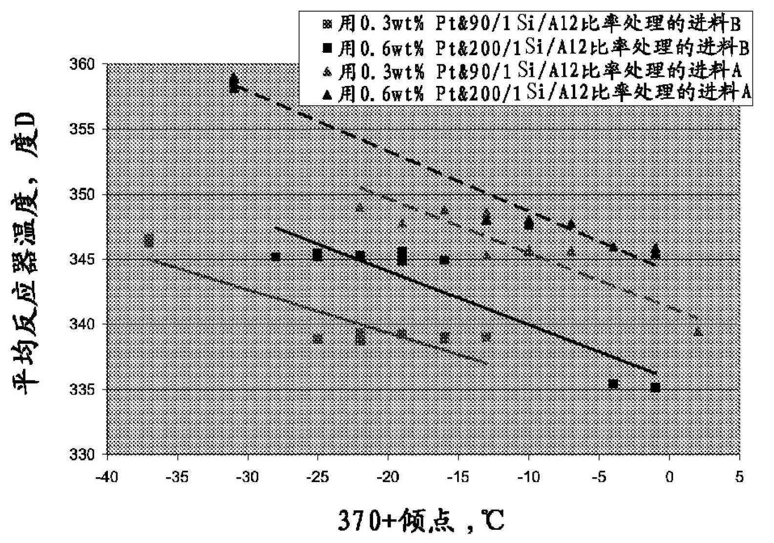
[0041] Four different feeds having the properties listed in Table 1, namely light neutral (LN) and heavy neutral (HN) slack waxes, and LN and HN hydrocracking products. in 1hr -1 The liquid hourly space velocity (LHSV), 419Nm 3 / m 3 Hydrogen circulation rate, 107kg / cm 2 The process is carried out at a pressure and an average reaction temperature adjusted to produce lube oil fractions having substantially the same pour point. The results are ...
Embodiment 2
[0046] This example is a hypothetical example using the dewaxing catalyst and process conditions of Example 1 to treat a similar set of feeds, but with higher levels of sulfur and nitrogen impurities. The operating temperature required to achieve the same 370°C + conversion as in Example 1 was calculated and the results are shown in Table 2.
[0047] Table 2
[0048]
[0049] Table 2 shows that, depending on the wax content of the feed, high sulfur and nitrogen levels can be tolerated using the catalyst of Example 1 at a nominal 365°C dewaxing temperature. Note that the conversion is the same in Example 2 as in Example 1, thus resulting in similar lubricating oil yields and properties.
Embodiment 3
[0051] In this example, the dewaxing catalyst of Example 1 was used to dewax two similar slack paraffin feeds that had been prepared with a conventional NiMo on alumina HDT catalyst, as specified in Table 3. Hydrotreating was previously carried out under similar conditions to that of , with temperatures adjusted to produce hydrotreated products with different sulfur contents.
[0052] table 3
[0053]
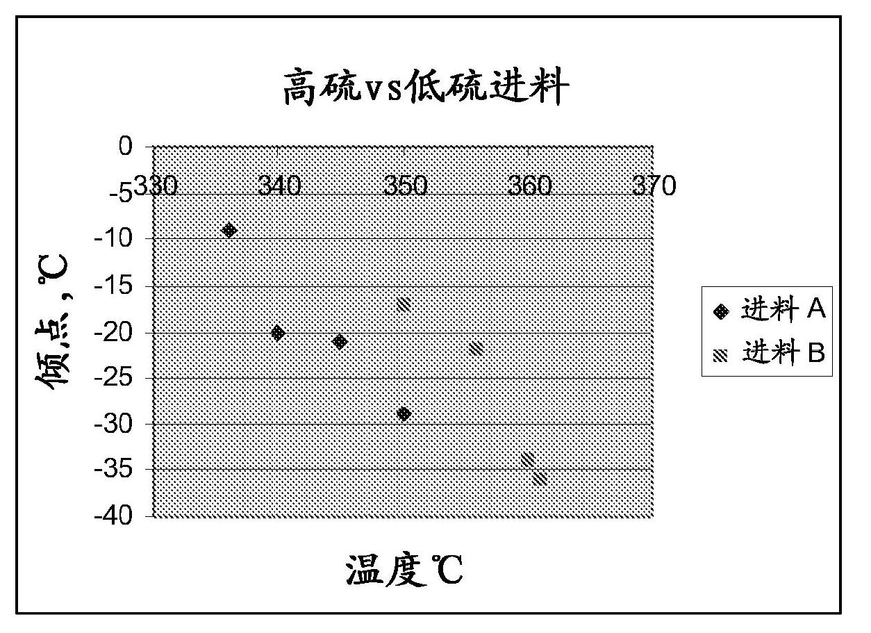
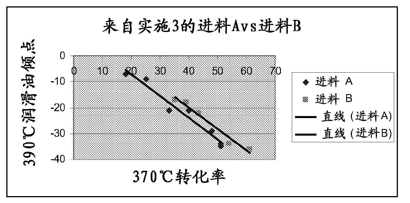
[0054] The resulting hydrotreated product was dewaxed to various pour points from -10 to -36°C using the dewaxing catalyst described in Example 1 and the results are shown in figure 1 and 2 middle. The feed properties for dewaxing are shown in Table 3 as "Product Properties" for the hydrotreatment step. figure 1 shows that pour points as low as -36°C can be achieved at reaction temperatures below 365°C, although slightly higher temperatures (approximately 5°C) are required to achieve the desired pour point for higher sulfur feeds . figure 2 It was shown that the effect...
PUM
 Abstract
Description
Claims
Application Information
 - R&D
- Intellectual Property
- Life Sciences
- Materials
- Tech Scout
- Unparalleled Data Quality
- Higher Quality Content
- 60% Fewer Hallucinations
Browse by: Latest US Patents, China's latest patents, Technical Efficacy Thesaurus, Application Domain, Technology Topic, Popular Technical Reports.
© 2025 PatSnap. All rights reserved.Legal|Privacy policy|Modern Slavery Act Transparency Statement|Sitemap|About US| Contact US: help@patsnap.com


