Film forming device and film forming method

A film-forming device and film-forming technology, applied in lighting devices, ion implantation plating, coating, etc., can solve the problems of large-scale device structure and a large number of masks, and achieve low device price, short production cycle, and large device size. small effect

Active Publication Date: 2012-09-19
ULVAC INC
View PDF7 Cites 13 Cited by
  • Summary
  • Abstract
  • Description
  • Claims
  • Application Information

AI Technical Summary

Problems solved by technology

[0015] However, in the conventional in-line method, since the substrate and the mask are fixed and the film is formed while moving it integrally, a large number of masks are required.
[0016] Furthermore, in the case of fabricating RGB devices by separate coating, three in-line circuits are required, and there is a problem that the device structure becomes large-scale.

Method used


Image

  • Film forming device and film forming method
  • Film forming device and film forming method
  • Film forming device and film forming method

Examples


Embodiment Construction

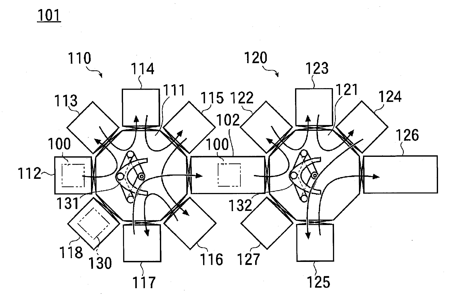
[0053] The film forming apparatus of the present invention is described as an example in which an organic thin film such as a light emitting layer of an organic EL element is sequentially formed on a substrate 12 . figure 1 A schematic configuration diagram of the film forming apparatus 1 is shown.

[0054] The film forming apparatus 1 has a plurality of film forming chambers 24 , 25 , and 26 .

[0055] The film-forming device 1 has three film-forming chambers 24, 25, and 26 here, and the three film-forming chambers 24, 25, and 26 are respectively referred to as the first, second, and third film-forming chambers below. 2. The third film forming chambers 24 , 25 , and 26 are arranged in series in this order.

[0056] Here, the first transfer chamber 23 is disposed adjacent to the first film formation chamber 24 , and the substrate carry-in chamber 22 and the mask carry-in chamber 31 are respectively disposed adjacent to the first transfer chamber 23 . Further, a second trans...


PUM


Abstract

Disclosed are a film forming device and film forming method which are low cost, adaptable to larger sized substrates, and have a short tact time. A substrate holding frame (12), onto which a substrate (11) is mounted, is loaded into an evacuated vacuum chamber (41). The substrate (11) on the substrate holding frame (12) is brought to rest at a position facing a mask (15) on a mask holding frame (43) which is disposed between a substrate conveyance path and outlets (42c) of a vapor deposition source (42). The substrate holding frame (12) is then detached from conveyance members on a conveyance mechanism (51) and the underside of the substrate (11) is held to the surface of a substrate attraction plate (81b) by electrostatic attraction. Subsequently, the mask (15) is aligned to the substrate (11), and with both the substrate (11) and the mask (15) brought to rest facing the vacuum chamber (41), the vapor of a film-forming material is emitted from the outlets (42c), forming a film on the surface of the substrate (11) from the vapor. After the film is formed, the substrate holding frame (12) on which the substrate (11) is mounted is unloaded to the outside of the vacuum chamber (41) while the mask remains mounted on the mask holding frame (43) in the vacuum chamber (41).

Description

technical field [0001] The present invention relates to a film forming device and a film forming method, and particularly relates to a technology suitable for the manufacture of organic EL elements. Background technique [0002] Currently, there are film-forming devices of a cluster system and an in-line system among film-forming devices for organic EL elements. Figure 10 An example of the structure of the film forming apparatus 101 of the cluster system is shown, Figure 11 An example of the configuration of the in-line film forming apparatus 201 is shown. [0003] In the case of the cluster-type film forming apparatus 101, as Figure 10 As shown, the first and second film forming apparatuses 110 and 120 of a single-piece type are connected through a transfer chamber 102 , and transfer robots 131 and 132 are provided in respective transfer chambers 111 and 121 . [0004] In the first film forming apparatus 110, the substrate 100 carried in from the carry-in chamber 112 of...

Claims


Application Information

Patent Timeline
Patent Type & Authority Applications(China)
IPC IPC(8): C23C14/24H01L51/50H05B33/10
CPCC23C14/56C23C14/042C23C14/12H05B33/10
Inventor 深尾万里菊地博
Owner ULVAC INC
Why Eureka
Try Eureka