Roll-over sucker elevator

A lifter and suction cup technology is applied in the field of automatic turning devices for workpieces on conveying lines, which can solve the problems of unsynchronized lifting, moving and turning actions, complex structure, large volume, etc. The effect of fewer types of parts

Active Publication Date: 2012-09-26
MIRACLE AUTOMATION ENG CO LTD
View PDF6 Cites 20 Cited by
  • Summary
  • Abstract
  • Description
  • Claims
  • Application Information

AI Technical Summary

Problems solved by technology

At present, the commonly used structure in China is that the lifting, moving and turning actions cannot be realized synchronously....

Method used


Image

  • Roll-over sucker elevator
  • Roll-over sucker elevator
  • Roll-over sucker elevator

Examples


Embodiment Construction

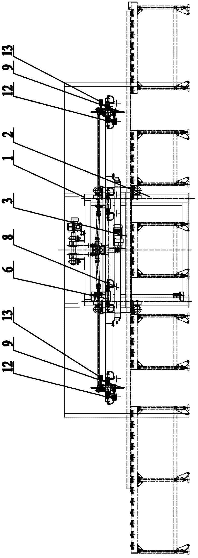
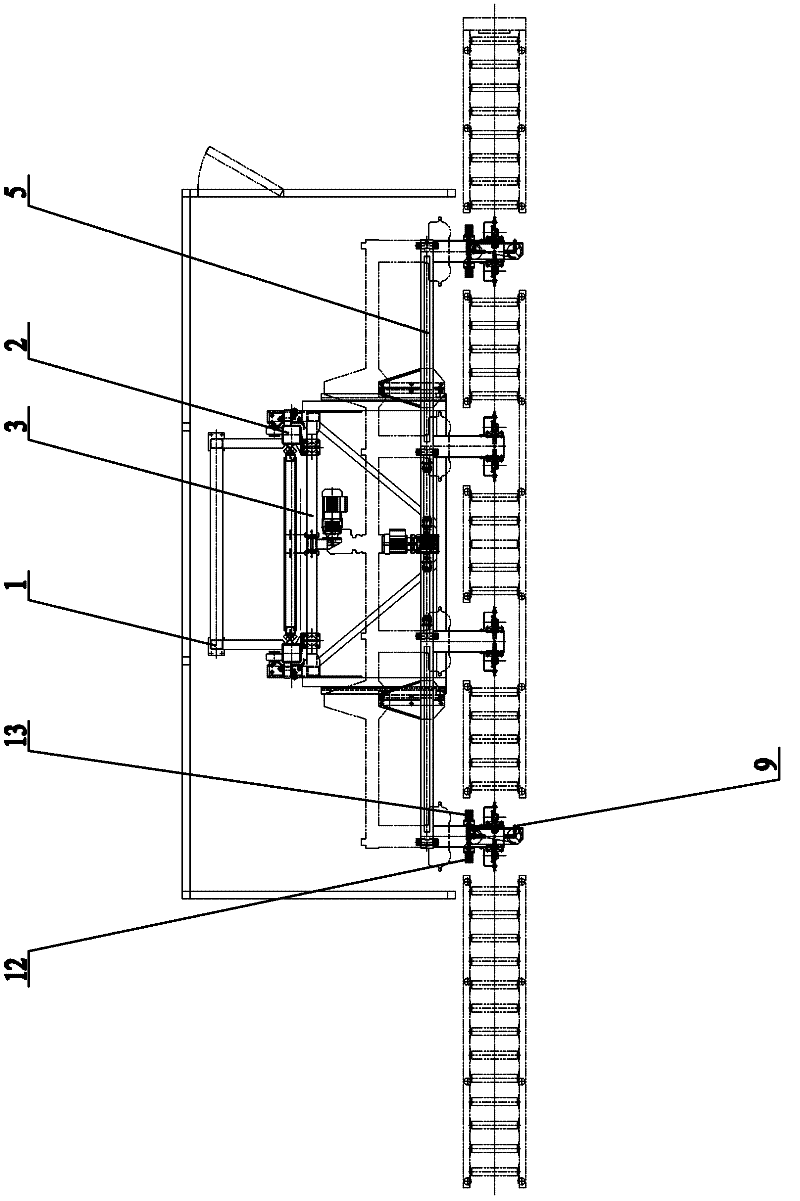
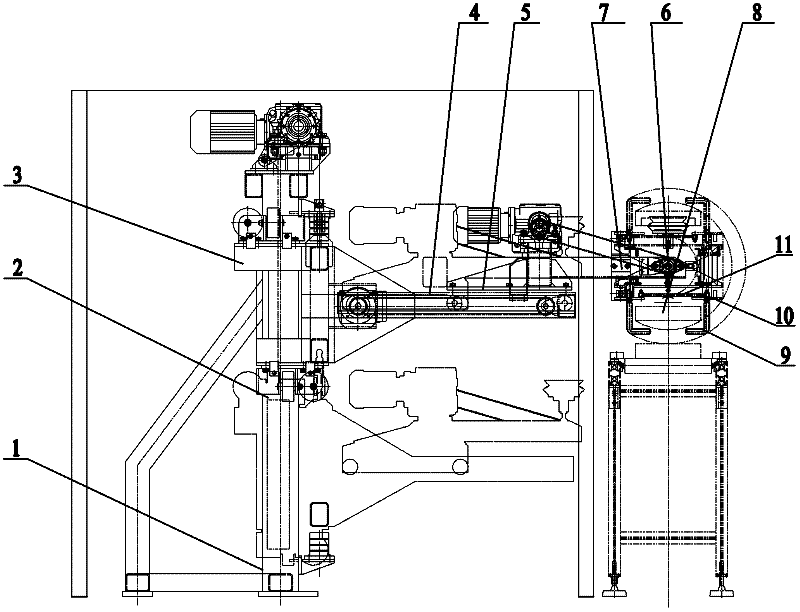
[0012] The present invention will be further described below in conjunction with specific drawings and embodiments.

[0013] As shown in the figure: the vertical guide rail 2 is fixed on the column 1, the lifting carriage 3 is slidably connected to the vertical guide rail 2, and the horizontal guide rails arranged horizontally in the left and right directions are fixed on the lifting carriage 3 4. A transverse carriage 5 is slidably connected to the transverse guide rail 4, and the turning frame on the transverse carriage 5 is provided with a turning shaft 6 arranged horizontally in the inner and outer directions. Suction cup 8 is provided.

[0014] Rotate the anti-drop bar 9 that is positioned at both ends sucker 8 both inside and outside of head and tail and be installed with the anti-drop bar 9 of vertical bending shape, be fixed with rotating push plate 10 on the anti-drop bar 9, one end of a connecting rod 11 is fixed on On one of the anti-drop bars 9, the other end of t...


PUM


Abstract

Belonging to the technical field of conveying machinery, the invention especially relates to a workpiece automatic roll-over device used in transfer lines. A vertical guide rail is fixed on an upright post. An elevating carriage is connected to the vertical guide rail in a sliding way. A transverse guide rail arranged in horizontally left and right direction is fixed on the elevating carriage. A transverse carriage is connected to the transverse guide rail in a sliding way. A roll-over shaft arranged in horizontally internal and external direction is mounted on the transverse carriage in a rotating way. A roll-over stand is fixed on the roll-over shaft. A sucker is fixed on the roll-over stand. Compared with common roll-over mechanisms, the roll-over device of the invention has the advantages of reasonable structure, few varieties of components, and installation, manufacturing and maintenance convenience, and can be used in the production lines of automobiles, household electrical appliance, and other industries. With a single machine, multi-moving operation is realized, the worker labor intensity is reduced, the assembling time is reduced, and the work efficiency is improved. Production line modular combination installation can be realized.

Description

technical field [0001] The invention belongs to the technical field of conveying machinery, and in particular relates to an automatic turning device for conveying line workpieces. Background technique [0002] In the conveying equipment of the automatic production line, according to the requirements of the production process beat, the workpiece needs to be automatically turned over at a specific station to meet the assembly requirements. However, the commonly used structure in China is that the lifting, shifting and turning actions cannot be realized synchronously. Most adopt the split structure to realize three kinds of actions, the structure is complex and the volume is large, and the efficiency is low. Contents of the invention [0003] The object of the present invention is to overcome the deficiencies in the prior art, and provide a reversing suction cup elevator with reasonable structure, few types of parts, convenient installation, manufacture and maintenance, and ...

Claims


Application Information

Patent Timeline
IPC IPC(8): B65G47/248
Inventor 张元兴蒋正兵李锋宝
Owner MIRACLE AUTOMATION ENG CO LTD
Why Eureka
Try Eureka