System for monitoring energy consumption of air conditioner

A monitoring system and air conditioning technology, applied in heating and ventilation control systems, signal transmission systems, non-electrical signal transmission systems, etc., can solve the problem that there is no interface for collecting energy consumption data, it is not suitable for quantitative management of air conditioning, and the monitoring network cannot be very efficient. Good adaptation to other problems, to achieve the effect of wide coverage, reducing the amount of communication data, and avoiding communication delays

Inactive Publication Date: 2012-09-26
潘桃园
View PDF6 Cites 14 Cited by
  • Summary
  • Abstract
  • Description
  • Claims
  • Application Information

AI Technical Summary

Problems solved by technology

For example, the Chinese invention patent whose publication number is CN101110097A discloses a kind of energy-saving control by controlling the power supply of air-conditioning equipment or central air-conditioning terminal equipment through the switch of the window. This invention is not suitable for the quantitative management of air-conditioning in current enterprises and institutions. There is no interface for collecting energy consumption data, and there is no centralized monitoring equipment
There is also an energy-saving control system based on the Internet of Things and wireless sensor network technology. Due to the small signal range of the wireless sensor network, the number of connections between the base station and the terminal is limited, generally less than 10, which limits its practicability
The well-known RS-485 bus network, because its communication signal voltage is within 6.8V, the maximum number of devices connected to a single RS-485 interface chip is 128 in theory, but the number of devices that can actually be connected is far less than this number, increasing RS-485 The 485 hub can solve the problem of the number of connections, but for the overall scattered and partially centralized structure of the equipment, the monitoring network of the RS-485 bus structure cannot be well adapted

Method used


Image

  • System for monitoring energy consumption of air conditioner
  • System for monitoring energy consumption of air conditioner
  • System for monitoring energy consumption of air conditioner

Examples


Embodiment Construction

[0020] The embodiments of the present invention will be further described in detail in conjunction with the accompanying drawings. The following embodiments are only descriptive, not restrictive, and cannot limit the protection scope of the present invention.

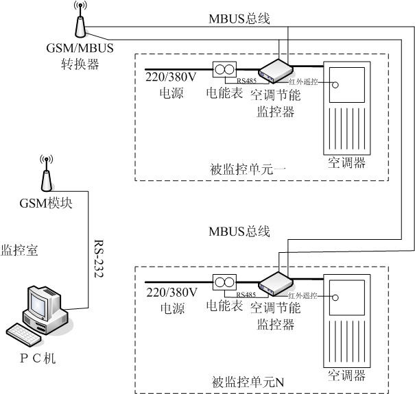
[0021] attached figure 1 The topological structure of the hardware device of the embodiment of the present invention is shown, which is geographically distributed into two areas: a monitoring room and a monitored area. The monitoring room is composed of a PC and a GSM module, which are connected by an RS-232 serial cable or a USB-to-serial cable. The GSM module needs to insert a SIM card when it is working. The monitored area refers to a relatively independent building. The air-conditioning equipment in the building and the room of the building, and the GSM / MBUS converter in the monitored area also insert the SIM card, and the numbers of the two cards are different. The mains 220V / 380V power supply in the room (monito...


PUM


Abstract

The invention discloses a system for monitoring the energy consumption of an air conditioner. The system comprises a PC (personal computer) machine and a GSM (global system for mobile communications) module or mobile phone in a monitoring room, a GSM/MBUS converter in a building, and an electric energy meter, an air-conditioning energy-saving monitor and an air conditioner in a monitored unit, wherein the GSM/MBUS converter is composed of an MBUS bus interface, a 30V/15V level conversion circuit, a current/voltage conversion circuit, an RS-232 interface, a GSM module, an MCU (micro control unit) with two serial ports, and a 220V-to-30V/5V power module; and the air-conditioning energy-saving monitor is composed of an ammeter pulse input, a human-body infrared sensor input, a temperature/humidity sensor input, an infrared remote control output, an MBUS bus, an RS-485 bus, an EEPROM (electrically erasable programmable read-only memory), an electromagnetic relay output interface, and a 220V/ 380V-to-12V/5V power module. The system disclosed by the invention is applicable to the centralized monitoring of air conditioners in offices of enterprises and public institutions.

Description

technical field [0001] The invention relates to a remote monitoring and control technology, in particular to a distributed energy consumption monitoring system combined with a GPRS wireless network and an MBUS and RS-485 wired network, specifically an air conditioner energy consumption monitoring system. Background technique [0002] At present, the technology applied to the energy saving and control of air conditioners mainly uses a single air conditioner as the control object, detects environmental parameters through infrared human body sensing equipment, temperature sensors, etc., and automatically adjusts the operating status of the air conditioner to achieve the purpose of saving electricity. For example, the Chinese invention patent whose publication number is CN101110097A discloses a kind of energy-saving control by controlling the power supply of air-conditioning equipment or central air-conditioning terminal equipment through the switch of the window. This invention ...

Claims


Application Information

Patent Timeline
Patent Type & Authority Applications(China)
IPC IPC(8): G08C23/04F24F11/02
CPCY02B60/50
Inventor 潘桃园
Owner 潘桃园
Why Eureka
Try Eureka