Metal wire clip of tail end fixing cable

A technology for fixing cables and metal wires, which is applied in the direction of devices for relieving stress at wire connections, components of connection devices, coupling devices, etc., and can solve the problem of reliability, cable crimping, and airtightness affecting electromagnetic interference shielding effect, model Diversification affects management costs, poor electromagnetic interference shielding effect, etc., to achieve the effect of solving electromagnetic interference shielding problems, convenient shielding layer grounding, and strong anti-interference ability

Inactive Publication Date: 2012-09-26
SHANGHAI AEROSPACE SCI & IND ELECTRIC APPLIANCE RES INST
View PDF7 Cites 9 Cited by
  • Summary
  • Abstract
  • Description
  • Claims
  • Application Information

AI Technical Summary

Problems solved by technology

[0003] , Dimensional intermatability is poor: the inner diameter of the outlet barrel of the integrated structure needs to be determined with the outer diameter of the cable, and cables with different wire diameters need to be equipped with corresponding outlet barrels, which increases the processing cost of parts, and the diversification of models affects management cost
[0004] 2. Poor electromagnetic interference shielding effect: the outlet barrel and the cable are crimped and fixed once, and the shielding layer of the cable can only be welded on the inner wall of the metal clamp or the shell of the electrical connector to achieve grounding. The reliability of welding and the cable pressure The tightness of the connection directly affects the quality of the electromagnetic interference shielding effect

Method used


Image

  • Metal wire clip of tail end fixing cable
  • Metal wire clip of tail end fixing cable
  • Metal wire clip of tail end fixing cable

Examples


Embodiment 1

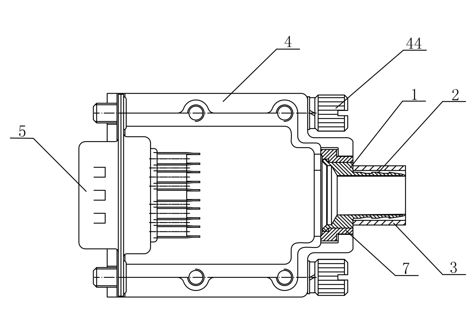
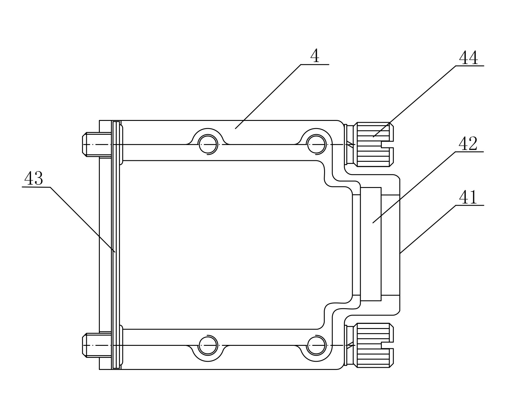
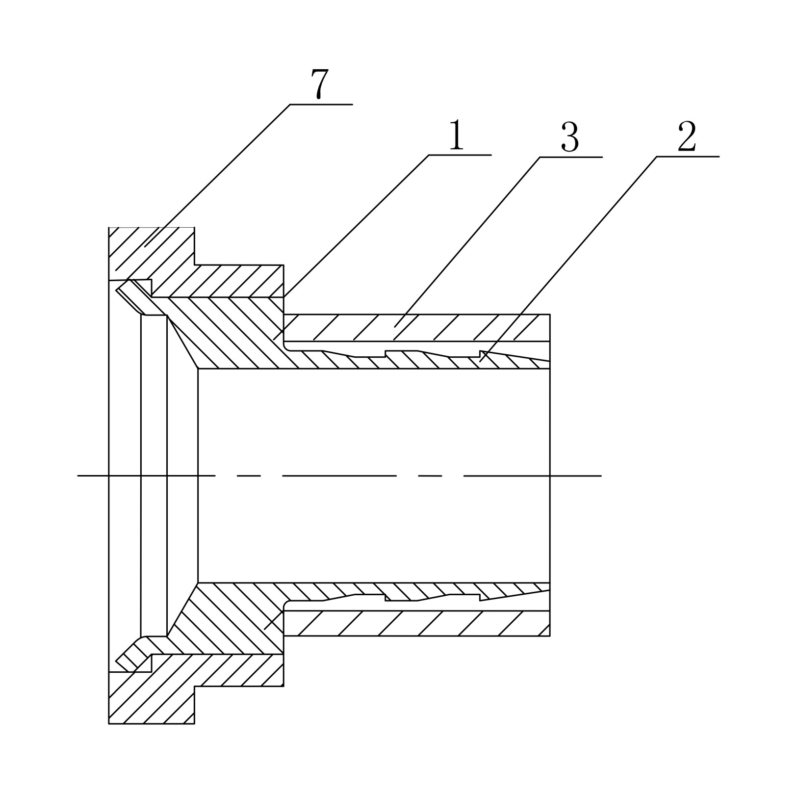
[0018] See attached figure 1 , the present invention is made up of metal wire clamp 4, connector 5 and outlet sleeve 1, and metal wire clamp 4 is the line box that is provided with cable port 41 and connector port 43, and outlet sleeve 1 and connector 5 are respectively arranged on metal On the ports on both sides of the clamp 4. The outlet sleeve 1 is composed of a flange 7, an outlet barrel 2 and a crimping pipe 3. The flange 7 is a rectangular plate with a central through hole 12 and a step 17; the central through hole 12 is symmetrically provided with a flat groove 10, one port is provided with a ring groove 16; the outlet tube 2 is provided with a platform 13 in the middle and a casing with a serrated cylindrical surface 14 and a knurled cylindrical surface 12 at both ends, the platform 13 is symmetrically arranged and has a complementary structure with the flat groove 10; the outlet barrel 2 is set with the flange 7, and the knurled cylindrical surface 12 and the ring g...


PUM


Abstract

The invention discloses a metal wire clip of a tail end fixing cable, which comprises the metal wire clip, a connector and an outgoing wire sleeve, and is characterized in that the outgoing wire sleeve comprises a flange, an outgoing wire tube and a wire pressing tube; the flange is a rectangular plate which is provided with a central through hole and a step; the outgoing wire tube is a sleeve with a platform in the middle and respectively a saw tooth-shaped cylindrical surface and a knurled cylindrical surface on both ends; the outgoing wire tube is sleeved with the flange, and the knurled cylindrical surface of the outgoing wire tube and a circular groove are in flanging compaction riveting; the wire pressing tube is sleeved on the saw tooth-shaped cylindrical surface; a port on one side of the metal wire clip is provided with a groove; the outgoing wire sleeve is sleeved in the groove; and the connector is fixedly arranged on the port on the other side of the metal wire clip through a screw. Compared with the prior art, the metal wire clip of the tail end fixing cable has a simple structure and is convenient to assemble, the wire clamping is firm and durable, the grounding of a shield layer is convenient, the anti-disturbance from environment is strong, the cable alternation is good, and outgoing wire tubes which are matched with the cables diameter can be selected, combined and used on demand.

Description

technical field [0001] The invention relates to the technical field of electrical connectors, in particular to a metal wire clip used for fixing cables at the tail end of an electrical connector. Background technique [0002] In the application of electrical connectors, there are many electrical connectors that need to weld wires at the tail of the contact terminal. Among them, there are a series of factors such as protecting the welding part of the connector, supporting hot plugging and insulation blocking of some devices, and electromagnetic interference shielding. Considering that it usually needs to be used with metal wire clips. Due to the metal clamp of the prior art, the cable at the tail end is fixed by crimping the integrated outlet sleeve and the cable. Although the structure is simple, there are the following problems: [0003] , Dimensional intermatability is poor: the inner diameter of the outlet barrel of the integrated structure needs to be determined with ...

Claims


Application Information

Patent Timeline
Patent Type & Authority Applications(China)
IPC IPC(8): H01R13/502H01R13/58H01R13/6592
Inventor 戚志成
Owner SHANGHAI AEROSPACE SCI & IND ELECTRIC APPLIANCE RES INST
Why Eureka
Try Eureka