
Microcomputer-type power transmission temporary protection device

A technology of temporary protection and model, applied in emergency protection circuit devices, electrical components, etc., can solve the problems of current loop failure, low setting accuracy, serious secondary burden, etc. High-precision, full-featured effects

Inactive Publication Date: 2012-09-26
国网黑龙江省电力有限公司超高压公司 +1
View PDF6 Cites 0 Cited by
  • Summary
  • Abstract
  • Description
  • Claims
  • Application Information

AI Technical Summary

Problems solved by technology

[0011] The present invention aims to solve the problems of low temporary protection sensitivity, low setting precision, serious secondary burden, and easy failure of the current loop in the existing temporary protection device for power transmission, thereby providing a temporary protection device for power transmission with a microcomputer device

Method used


Image

  • Microcomputer-type power transmission temporary protection device
  • Microcomputer-type power transmission temporary protection device
  • Microcomputer-type power transmission temporary protection device

Examples


specific Embodiment approach 1

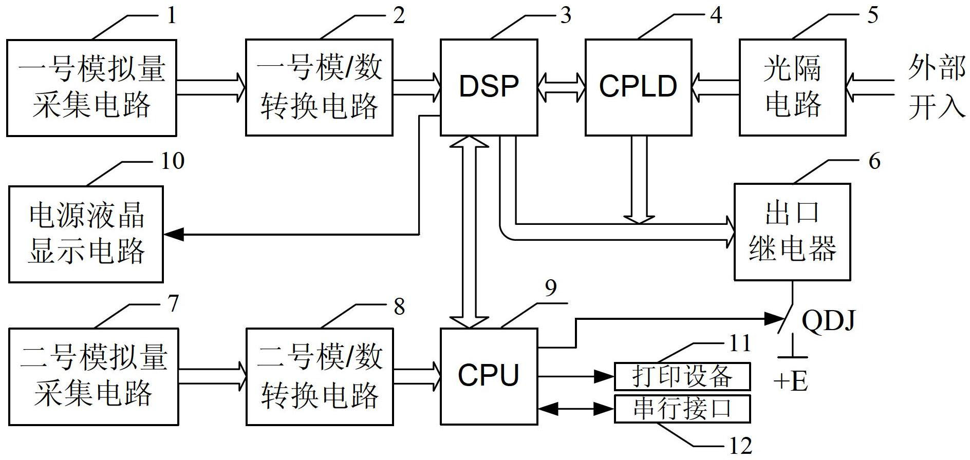
[0018] Specific implementation mode 1. Combination Figure 1 to Figure 3 Illustrate this specific embodiment, the microcomputer power transmission temporary protection device, it comprises No. 1 analog quantity acquisition circuit 1, No. 1 analog / digital conversion circuit 2, DSP3, CPLD4, optical isolation circuit 5, outlet relay 6, electromagnetic switch QDJ , No. 2 analog acquisition circuit 7, No. 2 analog / digital conversion circuit 8 and CPU9;

[0019] The analog quantity acquisition signal output end of the No. 1 analog quantity acquisition circuit 1 is connected with the analog quantity acquisition signal input end of the No. 1 analog / digital conversion circuit 2; the digital signal output terminal of the No. 1 analog / digital conversion circuit 2 is connected with the DSP3 The digital signal input terminal is connected; the No. 1 signal input or output terminal of DSP3 is connected with the signal output or input terminal of CPLD4; the relay control signal output termina...

specific Embodiment approach 2

[0025] Specific embodiment two, the difference between this specific embodiment and the microcomputer power transmission temporary protection device described in specific embodiment one is that it also includes a power supply liquid crystal display circuit 10, and the display signal input terminal of the power supply liquid crystal display circuit 10 Connect with the display signal output terminal of DSP3.

[0026] In this embodiment, the current current value can be displayed in real time through the liquid crystal display circuit 10 of the power supply.

specific Embodiment approach 3

[0027] Specific embodiment three, the difference between this specific embodiment and the microcomputer power transmission temporary protection device described in specific embodiment one is that it also includes a printing device 11, and the printing device 11 communicates with the CPU9 through a serial or parallel data bus. connect.

[0028] This embodiment provides a printing device to realize the output of the current value.


PUM


Abstract

The invention discloses a microcomputer-type power transmission temporary protection device, and relates to a power transmission temporary protection device, in order to solve the problems that the existing power transmission temporary protection device is low in temporary protection sensitivity, is low in constant value setting accuracy and is serious in secondary burden, and a current loop is easily failed. Analog quantity acquisition signals of a No.1 analog quantity acquisition circuit are converted by a No.1 analog / digital conversion circuit, and then are input into a DSP (digital signal processor); the DSP and a CPLD (complex programmable logic device) perform data interaction; the relay control signal output end of the DSP and the replay control signal output end of the CPLD are both connected with a relay control signal input end of an outlet relay; one end of the outlet relay is connected with one end of an electromagnetic switch; analog quantity acquisition signals of a No.2 analog quantity acquisition circuit are converted by a No.2 analog / digital conversion circuit, and then connected with a digital signal input end of a CPU (central processing unit); the DSP and the CPU perform data interaction; and the CPU controls the electromagnetic switch to act. The microcomputer-type power transmission temporary protection device provided by the invention is suitable for power transmission temporary protection.

Description

technical field [0001] The invention relates to a temporary protection device for power transmission. Background technique [0002] The reliability of 500 kV backbone grid power supply is becoming more and more important, and with the rapid growth of the national economy, new 500 kV lines and transformers are becoming more and more frequent. When the new equipment is put into operation, considering the uncertainty of the new equipment and the temporary change of the system operation mode, it is necessary to ensure the safety and reliability of the new equipment and the safety of the original system from the aspect of relay protection. Therefore, it must be installed during power transmission temporary protection. [0003] If the temporary protection method is improper during the commissioning process, it may cause unnecessary actions of the protection, and even expand the accident when the fault occurs. Therefore, the reliability and safety of the 500 kV backbone grid power...

Claims


Application Information

Patent Timeline
Patent Type & Authority Applications(China)
IPC IPC(8): H02H7/26
Inventor 胡旻昊杨戈羊绛军
Owner 国网黑龙江省电力有限公司超高压公司
Learn More