3D-trench electrode detectors

A radiation detector and electrode technology, which is applied in the field of radiation detectors, can solve problems such as high depletion voltage, charge sharing, and unfavorable detectors, so as to minimize the concentration of highly uneven electric fields and overcome the existence of highly uneven electric fields , the effect of improving the energy resolution

Inactive Publication Date: 2012-09-26
BROOKHAVEN SCI ASSOCS
View PDF8 Cites 18 Cited by
  • Summary
  • Abstract
  • Description
  • Claims
  • Application Information

AI Technical Summary

Problems solved by technology

However, 3D detectors still have significant drawbacks and deficiencies, particularly at extremely high radiation
[0017] At least one such deficiency of 3D detectors is charge sharing due to close electrode spacing
This phenomenon can be particularly detrimental to detectors in high-energy physics applications
For example, it has been observed that after heavy irradiation, such as experienced in particle colliders, silicon lattices suffer from severe radiation-induced defects, which lead to excessive carrier trapping and ultimately poor carrier collection efficiency
Therefore, excessive radiation levels in conventional 3D detectors may cause: 1) a highly concentrated inhomogeneous electric field around the narrow junction electrode, which may induce intrinsic breakdown at or near the junction electrode; 3) long carrier drift times in low-field regions (causing incomplete charge collection); and 4) compared to 2D detectors with a thickness comparable to the pillar spacing of 3D detectors, requiring higher depletion voltage

Method used


Image

  • 3D-trench electrode detectors
  • 3D-trench electrode detectors
  • 3D-trench electrode detectors

Examples


Embodiment Construction

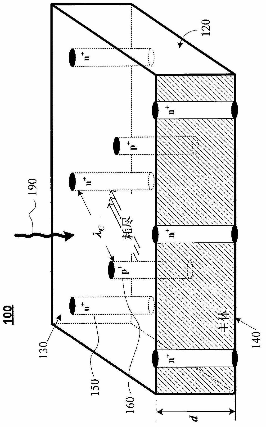
[0072] To avoid misunderstandings with other 3D technologies and detectors in nomenclature and structure (i.e., 3D stacking of detectors and electronics and 3D position-sensitive detectors), with respect to the above-mentioned conventional "3D detectors" shown in Fig. 1B, The 3D detector of the present invention is called a "3D trench electrode detector". In particular, several embodiments of new and novel 3D detectors are disclosed based on a first electrode configuration fabricated in the form of a "trench" surrounding a second electrode in the form of a rod or pillar. As used in this specification, the term "groove" generally means a deep and narrow groove or cutout having a predetermined width and depth. Therefore, this new type of 3D detector is often described as a "3D trench electrode detector", but for simplicity and brevity, the 3D trench electrode detector can also be referred to interchangeably as a "3D trench electrode detector". For the convenience of the reader,...


PUM


Abstract

A three-dimensional (3D) Trench detector and a method for fabricating the detector are disclosed. The 3D-Trench detector includes a bulk of semiconductor material that has first and second surfaces separated from each other by a bulk thickness, a first electrode in the form of a 3D-Trench, and a second electrode in the form of a 3D column. The first and second electrodes extend into the bulk along the bulk thickness. The first and second electrodes are separated from each other by a predetermined electrode distance, and the first electrode completely surrounds the second electrode along essentially the entire distance that the two electrodes extend into the bulk such that the two electrodes are substantially concentric to each other. The fabrication method includes doping a first narrow and deep region around the periphery of the bulk to form the first electrode, and doping a second narrow and deep region in the center of the bulk to form the second electrode.

Description

[0001] Cross References to Related Applications [0002] This application claims priority to 35 U.S.C. 119(e) of U.S. Provisional Application No. 61 / 252,756, filed October 19, 2009, the entire contents of which are hereby incorporated by reference. [0003] Statement of Government Licensing Rights [0004] This invention was made with Government support under Contract No. DE-ACO2-98CH 10086 awarded by the US Department of Energy. The US Government has certain rights in this invention. technical field [0005] The present invention relates to radiation detectors. In particular, the present invention relates to a three-dimensional detector, wherein at least one of the plurality of electrodes is configured as a three-dimensional trench electrode (three-dimensional trench electrode). Background technique [0006] Radiation detectors are well known and frequently used in various fields. Although originally developed for use in atomic, nuclear, and elementary particle physics,...

Claims


Application Information

Patent Timeline
Patent Type & Authority Applications(China)
IPC IPC(8): G01T1/24H01L21/02
CPCH01L27/1446H01L31/03529Y02E10/50H01L31/117H01L27/144H01L31/00
Inventor 李正
Owner BROOKHAVEN SCI ASSOCS
Why Eureka
Try Eureka