Vibrating mirror element and manufacturing method for same

A manufacturing method and mirror technology, applied to electrical components, microstructure devices composed of deformable components, optical components, etc., can solve the problems of low rigidity of the region, easy to produce bending deformation, etc.

Inactive Publication Date: 2012-09-26
FUNAI ELECTRIC CO LTD
View PDF6 Cites 5 Cited by
  • Summary
  • Abstract
  • Description
  • Claims
  • Application Information

AI Technical Summary

Problems solved by technology

Therefore, there is a problem that the rigidity of the region where the piezoelectric actuator is not installed is low, and bending deformation is likely to occur due to the self-weight of the driving part and the mirror part.

Method used


Image

  • Vibrating mirror element and manufacturing method for same
  • Vibrating mirror element and manufacturing method for same
  • Vibrating mirror element and manufacturing method for same

Examples


Embodiment Construction

[0056] Hereinafter, specific embodiments of the present invention will be described with reference to the drawings.

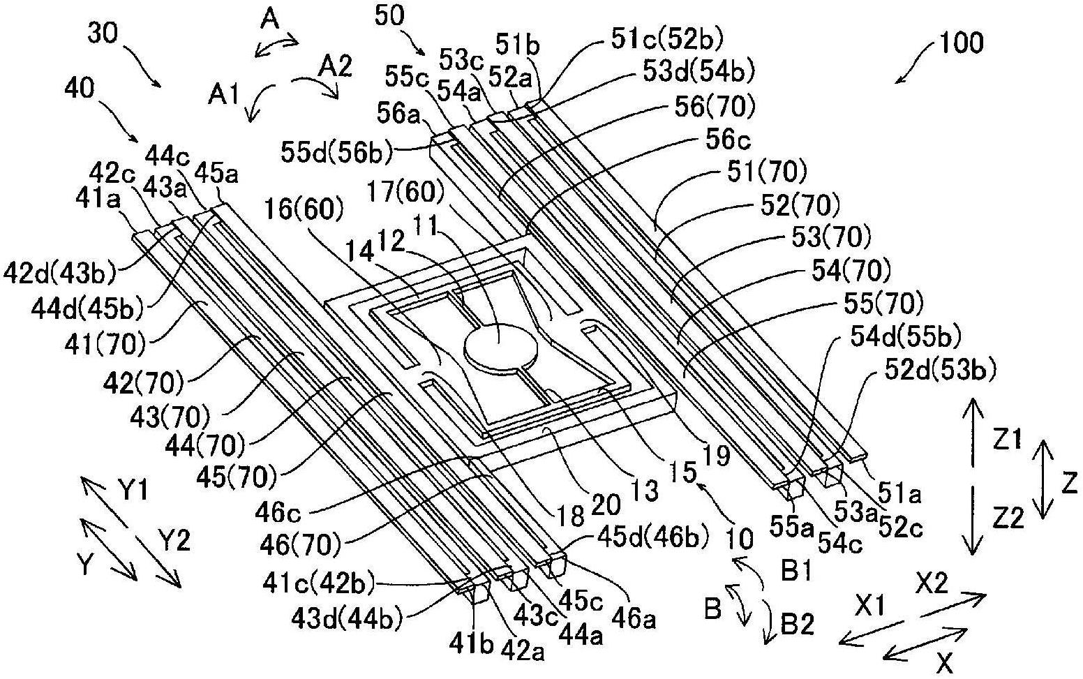
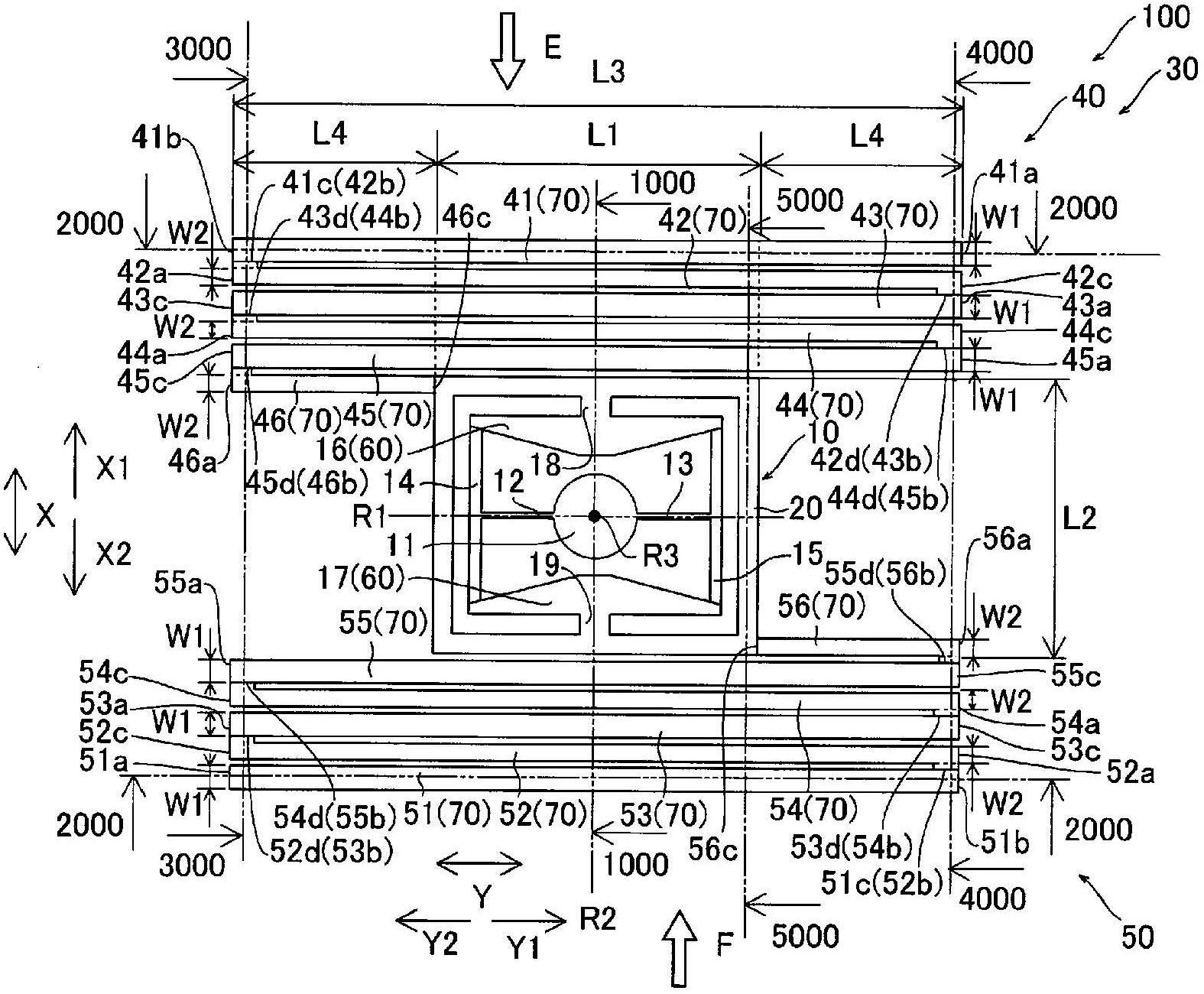
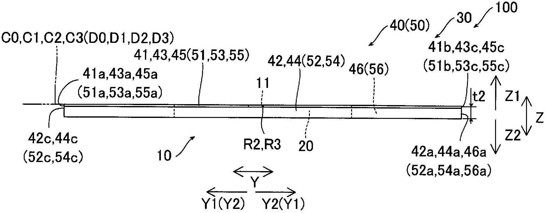
[0057] First, refer to Figure 1 to Figure 10 , the structure of the vibrating mirror element 100 according to one embodiment of the present invention will be described.

[0058] Such as Figure 1 to Figure 3 As shown, the vibrating mirror element 100 according to one embodiment of the present invention has: an X-direction light scanning unit 10 that scans with light in the X direction using a mirror 11 described later; a Y-direction light scanning unit 30 that uses The mirror 11 scans with light in the Y direction perpendicular to the X direction. In addition, if Figure 4 to Figure 8 As shown, the X-direction optical scanning unit 10 and the Y-direction optical scanning unit 30 are integrally formed on a general-purpose upper Si substrate 1 having a thickness t1 of about 0.1 mm. In addition, the X direction light scanning part 10 is an example of the "mir...


PUM

PropertyMeasurementUnit
thicknessaaaaaaaaaa
thicknessaaaaaaaaaa
thicknessaaaaaaaaaa

Abstract

Disclosed is a vibrating mirror element which can suppress the occurrence of deflection deformation in a support section. A vibrating mirror element (100) is provided with: a mirror section (10); deformable drive sections (41, 43, 45, 51, 53, 55); and support sections (42, 44, 46, 52, 54, 56) which are connected by the side of end sections (42a, 44a, 46a, 52a, 54a, 56a) thereof to connection sections (41c, 43d, 45d, 51c, 53d, 55d) on one side of the drive sections. The thickness of the support sections is greater than the thickness of the drive sections.

Description

technical field [0001] The present invention relates to a vibrating mirror element and a method for manufacturing the vibrating mirror element, and more particularly to a vibrating mirror element having a driving unit and a method for manufacturing the vibrating mirror element having a driving unit. Background technique [0002] Conventionally, a vibrating mirror element having a drive unit and a method of manufacturing a vibrating mirror element having a drive unit are known. For example, JP-A-2009-223165 and JP-A-2008-257226 disclose such a vibrating mirror element and a method of manufacturing the vibrating mirror element. [0003] Japanese Patent Laid-Open No. 2009-223165 discloses a light deflector (light deflector). A common substrate of the light deflector is formed with: a pair of driving parts arranged in the X direction; , which is arranged in the X direction and sandwiched between the pair of driving parts, and is rotated by the pair of driving parts; the frame, ...

Claims


Application Information

Patent Timeline
Patent Type & Authority Applications(China)
IPC IPC(8): G02B26/10B81B3/00B81C1/00
CPCG02B26/0841G02B26/101G02B26/0858B81B3/00B81B7/02B81C1/00G02B26/10
Inventor 小寺秀俊神野伊策村山学藤井仁
Owner FUNAI ELECTRIC CO LTD
Why Eureka
Try Eureka