Automatic control water bath evaporation unit

A unit and water bath technology, applied in the fields of food, chemical industry, and medicine, can solve the problems of increasing concentration and extraction costs, low heat conduction efficiency, and reduction of concentration efficiency, and achieve the effects of shortening concentration time, increasing heat transfer coefficient, and improving concentration efficiency

Active Publication Date: 2012-10-03
温兄控股集团股份有限公司
View PDF10 Cites 1 Cited by
  • Summary
  • Abstract
  • Description
  • Claims
  • Application Information

AI Technical Summary

Problems solved by technology

[0002] At present, the enrichment unit mainly includes a heating system, a concentrator, a condenser, and a liquid collection tank. The heating system is mainly composed of an expansion tank, a water pump, and a heater. The concentrator mainly includes a heating chamber and an evaporation chamber. The condenser is connected to the evaporation chamber. When working, the heating medium enters the expansion tank, is pumped out by the water pump and sent to the heater for heating, and the heat medium enters the heating chamber to heat the material. After heat exchange, the medium flows back into the expansion tank to realize cyclic heating; The boiled material enters the evaporation chamber from the heating chamber, and the generated secondary steam is condensed by the condenser to form a liquid and enters the liquid collection tank for storage. Concentration; because the existing heating system continuously heats the heating medium, and after the heating chamber continues to supply heat for a period of time, the heat loss in the heating chamber is relatively small, if the heating system continues to heat the heating medium continuously Heating will inevitably result in a waste of resources and increase the cost of concentration and extraction; while most of the existing heating chambers use a jacketed heating method, which has low heat conduction efficiency and reduces the concentration benefit, thus increasing the concentration cost

Method used


Image

  • Automatic control water bath evaporation unit
  • Automatic control water bath evaporation unit
  • Automatic control water bath evaporation unit

Examples


Embodiment Construction

[0015] Embodiments of the present invention will be further described below in conjunction with accompanying drawings:

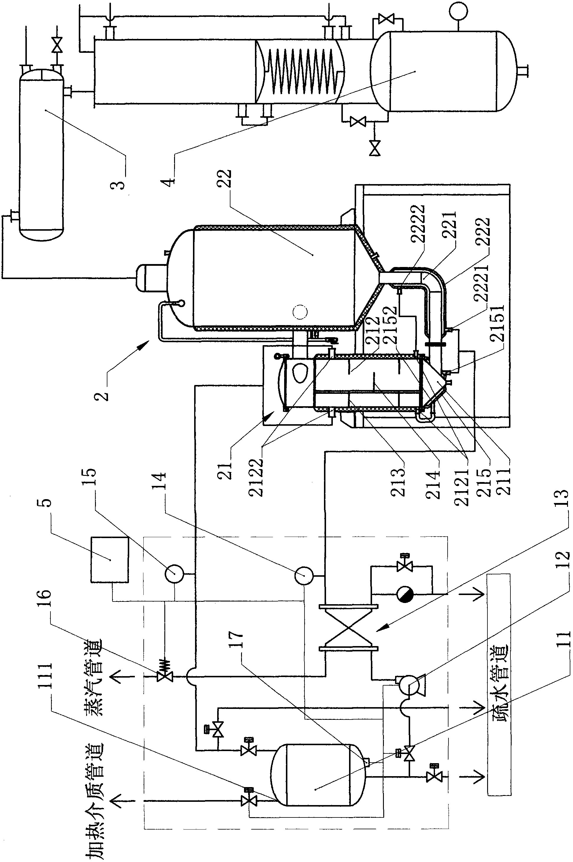
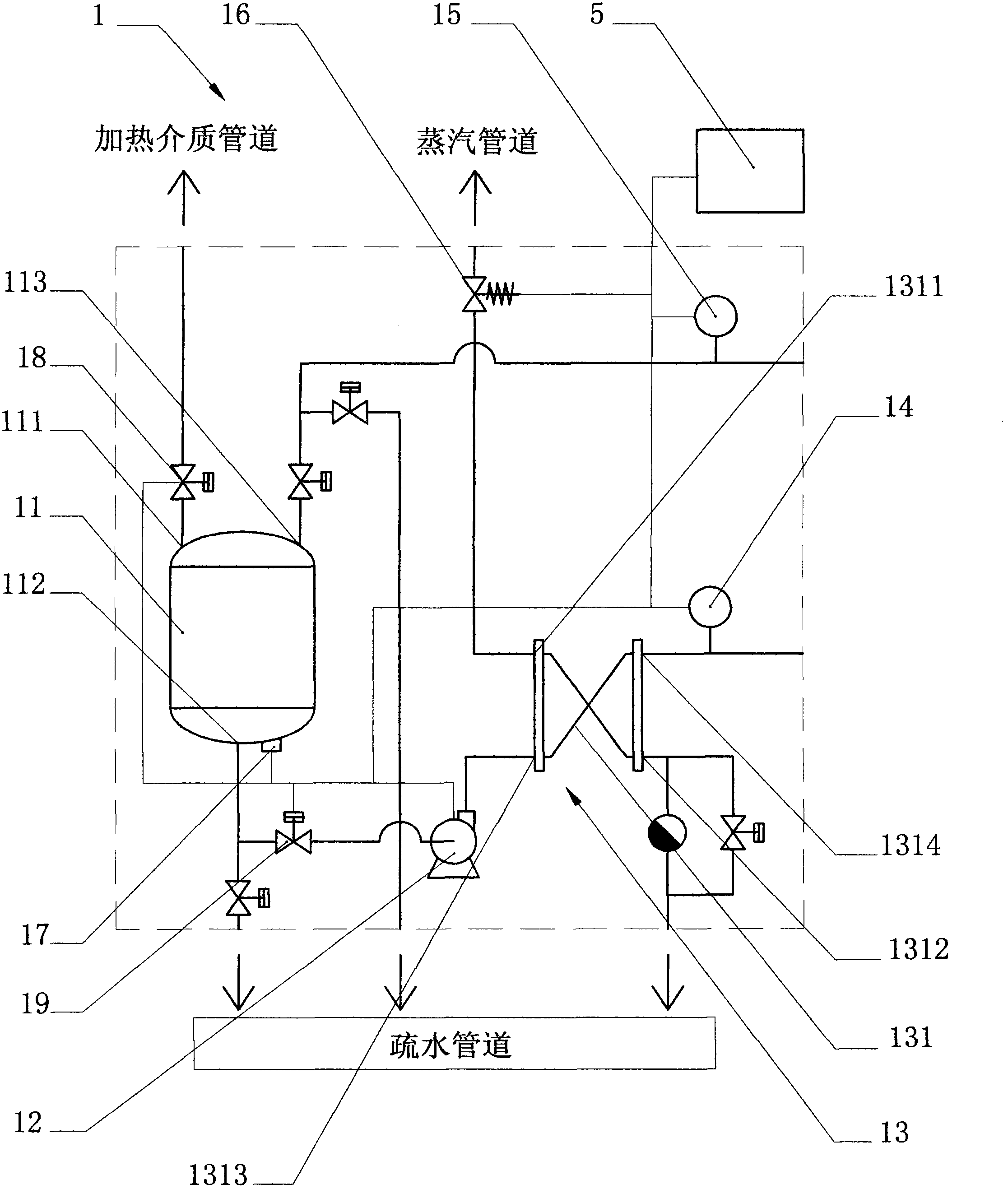
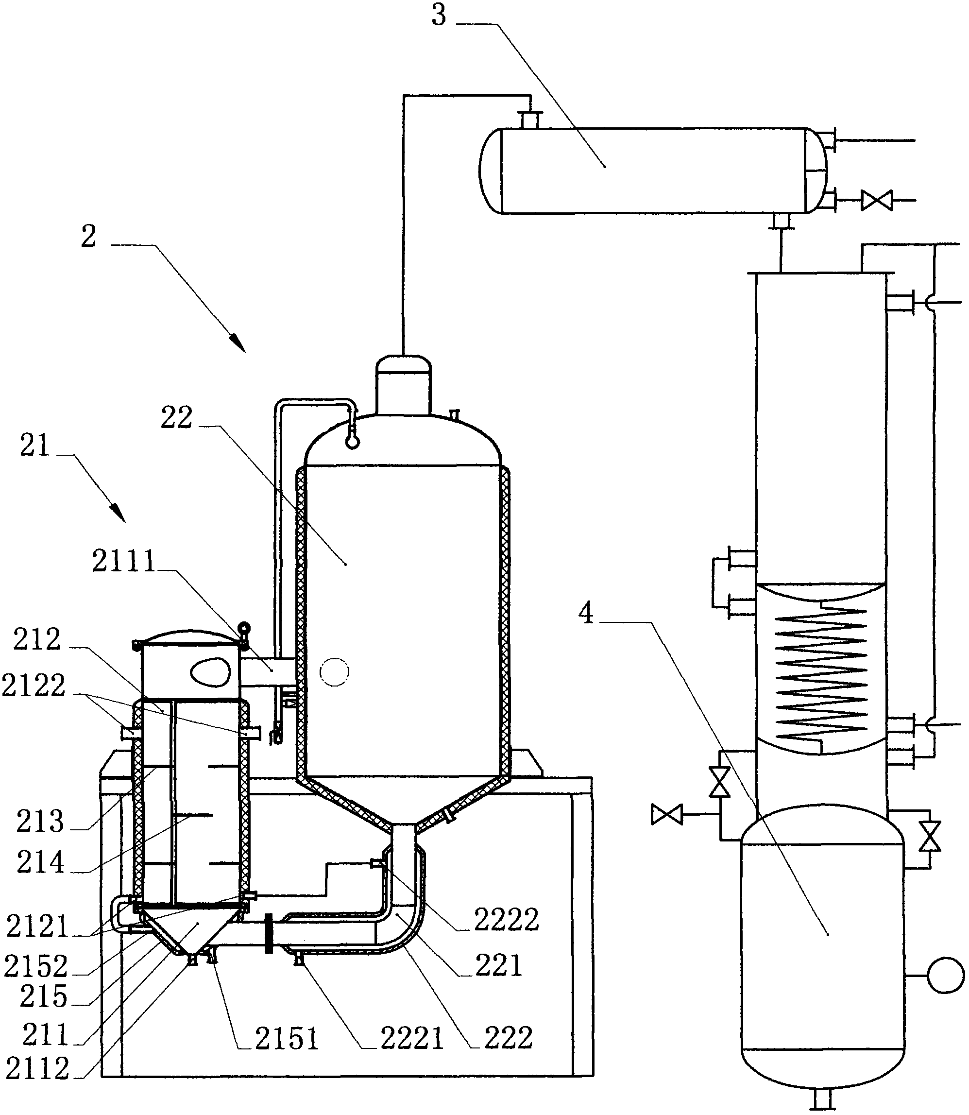
[0016] like Figure 1 to Figure 3 As shown, the present invention is an automatic control water bath evaporation unit, which includes a heating system 1, a concentrator 2, a condenser 3 and a liquid collection tank 4, and the heating system 1 includes inlets and outlets, ports 111, 112 and return ports 113 The expansion tank 11, the water pump 12, the heater 13, the concentrator 2 include a heating chamber 21 and an evaporation chamber 22, the heating chamber 21 is provided with a material chamber 211 and a heating chamber 212, and the heating chamber 212 is provided with a heating inlet and outlet, a port 2121 , 2122, the material chamber 211 is connected to the evaporation chamber 22 through the connecting pipe 2111, the bottom of the evaporation chamber 22 is provided with a circulation pipe 221 connected to the material chamber 211, the outlet of the exp...


PUM


Abstract

The invention relates to an automatic control water bath evaporation unit which is characterized in that a heating cavity is internally provided with a plurality of heating inlets and heating outlets, the plurality of heating inlets are respectively connected with an outlet of a heater, the plurality of heating outlets are respectively connected with a backflow port, a first temperature controller and a second temperature controller are arranged between the outlet of the heater and the plurality of heating inlets of the heating cavity and between the plurality of heating outlets and the backflow port respectively; the first temperature controller and the second temperature controller are both connected with a PLC (programmable logic controller) module, the heater is connected with the PLC module, and the PLC controls the starting and stopping of the heater. The beneficial effects are as follows: the PLC module is used to monitor in real time the temperature of a medium entering the heating cavity and flowing out of the heating cavity so as to turn on and turn off the heater, so that the heating stability of the heating cavity is guaranteed, energy sources are also saved at the same time, the medium is more uniformly distributed due to the plurality of heating inlets and outlets in the heating cavity, and a dead area is prevented from being produced in the heating cavity, so that the heating effect is much more balanced, the coefficient of heat conduction is increased, and the concentration benefit is improved.

Description

technical field [0001] The invention relates to an extracting and concentrating device, more specifically to an automatic control water bath evaporation unit, which is mainly used in the fields of medicine, food, chemical industry and the like. Background technique [0002] At present, the enrichment unit mainly includes a heating system, a concentrator, a condenser, and a liquid collection tank. The heating system is mainly composed of an expansion tank, a water pump, and a heater. The concentrator mainly includes a heating chamber and an evaporation chamber. The condenser is connected to the evaporation chamber. When working, the heating medium enters the expansion tank, is pumped out by the water pump and sent to the heater for heating, and the heat medium enters the heating chamber to heat the material. After heat exchange, the medium flows back into the expansion tank to realize cyclic heating; The boiled material enters the evaporation chamber from the heating chamber,...

Claims


Application Information

Patent Timeline
Patent Type & Authority Applications(China)
IPC IPC(8): B01D1/00B01D1/30
Inventor 姜瑞玉夏英杰张积贵项秉选姜瑞生姜沈阳项速张文
Owner 温兄控股集团股份有限公司
Why Eureka
Try Eureka