Crane main beam welding machine

A technology of cranes and welding machines, which is applied to welding equipment, welding rod characteristics, arc welding equipment, etc., can solve problems such as high labor intensity, increased turning hours, welding deformation, etc., to achieve the effect of reducing labor intensity and ensuring construction quality

Inactive Publication Date: 2012-10-03
HENAN MINE CRANE
View PDF5 Cites 8 Cited by
  • Summary
  • Abstract
  • Description
  • Claims
  • Application Information

AI Technical Summary

Problems solved by technology

This manual welding construction has the following disadvantages: 1. The labor intensity of the workers is relatively large; 2. The asynchronous welding construction of the four welds has low welding efficiency, and the welding stress of each weld is relatively large, which is prone to welding. Deformation affects the welding quality; 3. During manual welding, the main girder of the crane must be turned over with a turning device. Manufacturing cost of the main beam

Method used


Image

  • Crane main beam welding machine
  • Crane main beam welding machine
  • Crane main beam welding machine

Examples


Embodiment Construction

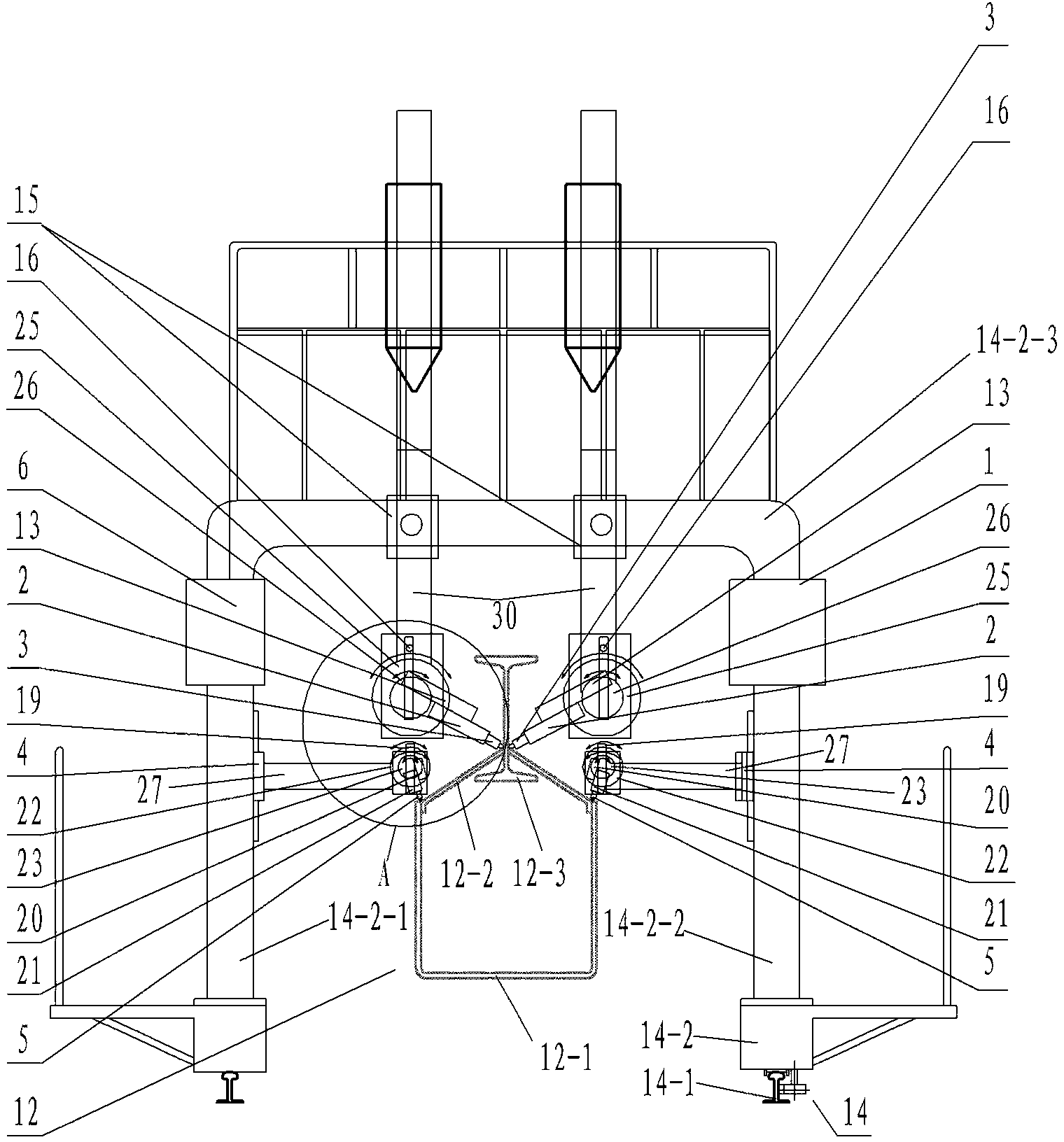
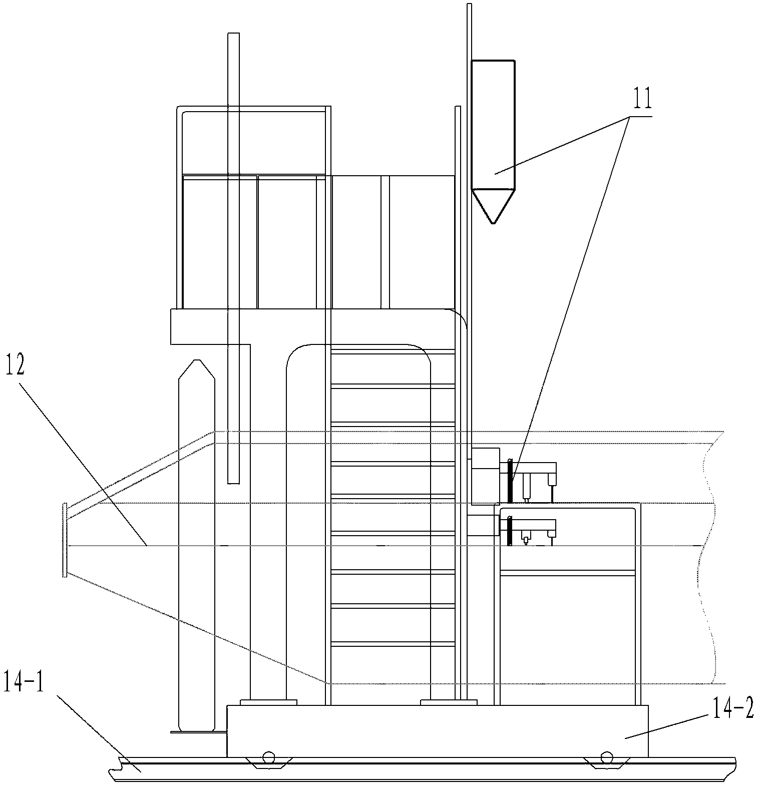
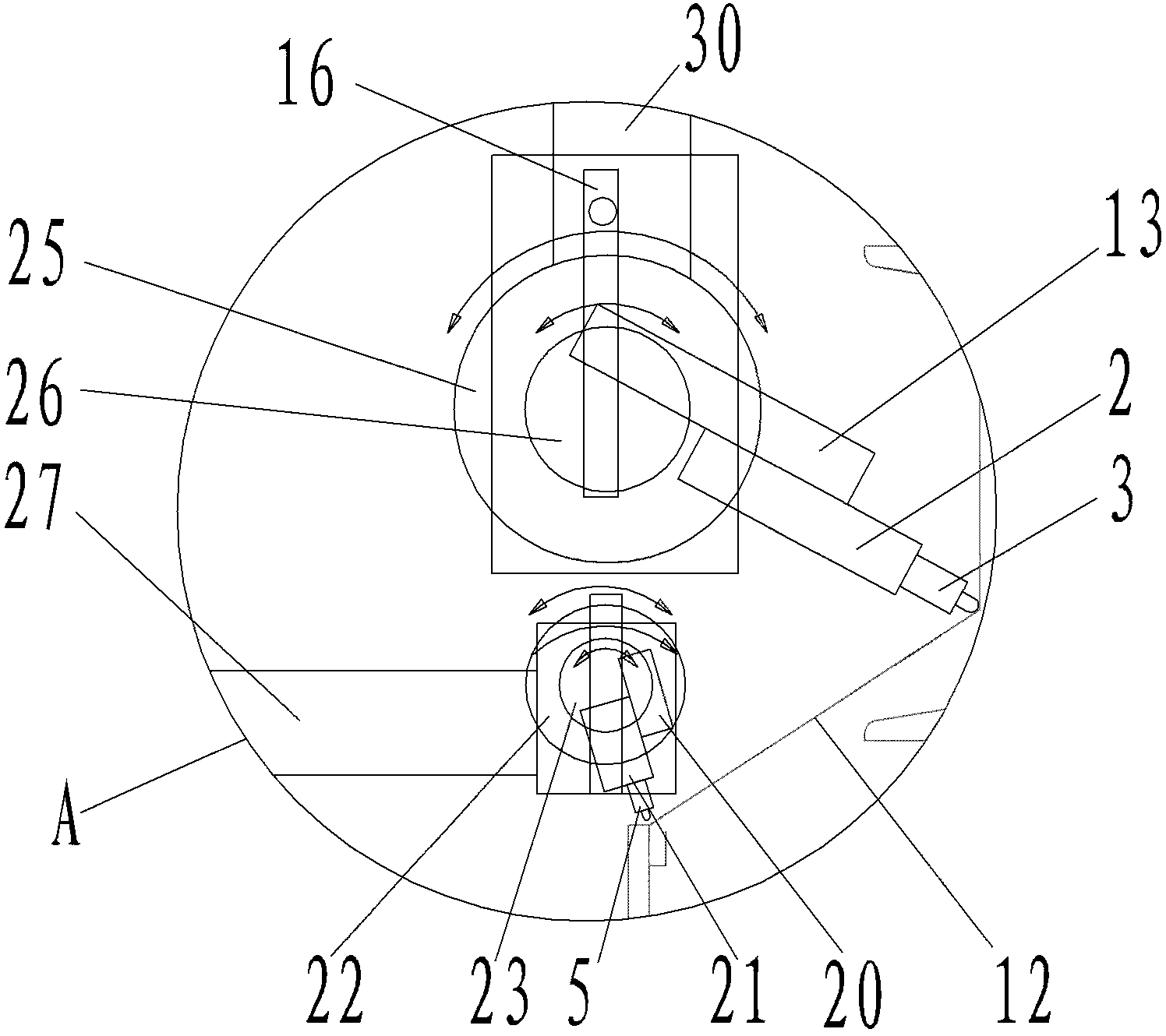
[0021] An example of a crane girder welding machine Figure 1~4 Shown: comprise frame 14, frame comprises fixed frame 14-1 and its upper sliding frame 14-2 that guides sliding assembly along the front and back direction, and movable frame 14-2 comprises the left side of lower end and fixed frame 14-1 guiding sliding assembly. Vertical frame 14-2-1, right vertical frame 14-2-2 and horizontal frame 14-2-3 erected on left and right vertical frame upper ends, left and right vertical frame and horizontal frame 14-2-3 constitute " door "Glyph structure, between the movable frame 14-2 and the fixed frame 14-1, be provided with the movable frame motor and the movable frame rack and pinion mechanism that drive the movable frame 14-2 to move along the front and rear direction, wherein in the movable frame rack and pinion mechanism The gear of the movable frame is connected with the output end of the movable frame motor, and the rack in the rack and pinion mechanism of the movable frame ...


PUM


Abstract

The invention relates to a crane main beam welding machine. The crane main beam welding machine comprises a fixed mount, a movable frame which is arranged on the fixed mount along horizontal direction in a guiding manner, the crane main beam welding machine further comprises a movable frame driving device which is in transmission connection with the movable frame and drives the movable frame to do reciprocating motion along the horizontal direction, and the movable frame is provided with a welding fun which is used for conducting welding construction on a position to be welded of a crane main beam. The invention provides a crane main beam welding machine which can lighten the labor intensity of workers in welding and manufacturing of the crane main beam.

Description

technical field [0001] The invention relates to a crane main girder welding machine used for crane main girder manufacturing. Background technique [0002] The main girder of the crane includes a beam box with a U-shaped groove in cross section, side plates respectively arranged at the edges of the notches on both sides of the beam box, and an I-beam set between the two side plates, wherein the lower ends of each side plate are respectively It is welded and fixedly connected with the upper end of the groove wall of the corresponding beam box, and the upper end of each side plate is welded and fixedly connected with the web plate of the corresponding side of the I-beam respectively. This means that the welding of four weld seams is required to complete the welding of a crane girder. The existing construction method is to weld the convenient one side weld seam earlier by hand, then the crane girder is turned over by the overturning device, and then Carry out the welding const...

Claims


Application Information

Patent Timeline
Patent Type & Authority Applications(China)
IPC IPC(8): B23K9/18B23K9/16B23K9/28
Inventor 高明利崔培军任海涛胡永堂冯俊张凯
Owner HENAN MINE CRANE
Why Eureka
Try Eureka