Tool for pressing small copper sleeve of engine connecting rod

A technology of engine connecting rods and press-fitting tools, which is applied in the direction of manufacturing tools, metal processing, metal processing equipment, etc., and can solve the problem that the positioning device cannot be completely fixed, the position of the copper sleeve press-fitting is difficult to grasp, and it is easy to fall into the press Problems in the machine tool to achieve the effect of preventing the deformation of the copper sleeve, convenient operation, and reducing shaking

Active Publication Date: 2012-10-03
HEBEI HUABEI DIESEL ENGINE
View PDF7 Cites 17 Cited by
  • Summary
  • Abstract
  • Description
  • Claims
  • Application Information

AI Technical Summary

Problems solved by technology

[0004] The current copper sleeve press-fitting process has the following disadvantages: only through the positioning shaft positioning, although there is a positioning sleeve to assist in determining the position and angle of the copper sleeve, the engine connecting rod is easy to shake and cannot be positioned accurately
The whole set of positioning device can not play the role of complete fixation, the position of the copper bushing is difficult to grasp, and it is easy to press the copper bushing crookedly
The positioning axis is manually controlled and cannot be fixed. It is inconvenient to operate, and it is easy to fall into the press machine tool, and the press-fitting efficiency is low.

Method used


Image

  • Tool for pressing small copper sleeve of engine connecting rod
  • Tool for pressing small copper sleeve of engine connecting rod
  • Tool for pressing small copper sleeve of engine connecting rod

Examples


Embodiment Construction

[0020] The present invention will be described in further detail below in conjunction with the accompanying drawings.

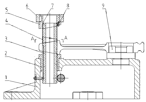
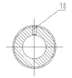
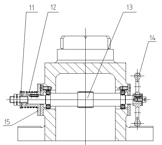
[0021] Pressing tools for the copper sleeve of the small end of the engine connecting rod, such as Figure 1-3 As shown, it is mainly composed of base 1, guide post 3, pressure sleeve 5, diamond-shaped positioning pin 9, gear shaft 13, and hand wheel 14.

[0022] like figure 1 As shown, the base 1 is fixed on the press, and the upper end surface of the base 1 is processed with two light holes. The light hole on the left side of the base 1 is fitted with the shaft sleeve 2 that matches the light hole, and the guide post 3 is placed in the shaft sleeve 2 . The guide post 3 is a stepped shaft that is thick at the bottom and thin at the top. The diameter of the bottom of the stepped shaft corresponds to the aperture of the small end of the connecting rod, and the diameter of the top of the stepped shaft is smaller than the aperture of the small end of the conne...


PUM


Abstract

The invention discloses a tool for pressing a small copper sleeve of an engine connecting rod. The tool comprises a liner plate, a pressing sleeve, and a base fixed on a press, wherein a guide post is arranged inside an unthreaded hole at one end of the base corresponding to the pressing sleeve; the guide post is a stepped shaft which is thick in lower part and thin in upper part; a rack is arranged at the lower end of the guide post; a gear shaft meshed with the rack is arranged at one side of the rack; a locating sleeve of which the upper end face is matched with an inclined plane of the copper sleeve and the diameter corresponds to the copper sleeve is arranged on the step of the guide post; a bush for pressing the copper sleeve is sleeved on the upper end of the guide post, wherein the lower end surface of the bush is matched with the inclined plane of the copper sleeve; a diamond locating pin matched with the aperture of a large end of the connecting rod is arranged at the other end of the base; an inner hole of the pressing sleeve is a step hole which is large in lower part and small in upper part; the aperture of the small end of the step hole is smaller than the guide post; and the lower end face of the pressing sleeve is the inclined plane matched with that of the small head of the connecting rod, and a locating pin is arranged at the position of the inclined plane on the lower end of the pressing sleeve, corresponding to the plane end of the small end of the connecting rod. The tool disclosed by the invention is accurate in positioning and convenient to operate, and the pressing efficiency is improved.

Description

technical field [0001] The invention relates to a pressing tool in the field of mechanical engineering, in particular to a tool for pressing a copper sleeve. Background technique [0002] The copper sleeve of the small head of the connecting rod of the engine plays the role of transmitting the cylinder explosion pressure and guiding, and its performance directly affects the quality and reliability of the engine. The small head of the engine connecting rod has a circular hole equipped with a copper sleeve, the end faces at both ends of the circular hole are sloped, and the edge of the large end of the circular hole slope is a plane. In order to match the inclined surface of the small head of the connecting rod, the copper sleeve is in the shape of a circular tube, both ends of the circular tube are inclined, and there is a radial semicircular gap at the intersection of the inclined surface at the lower end and the horizontal middle section. Due to the special structure of th...

Claims


Application Information

Patent Timeline
Patent Type & Authority Applications(China)
IPC IPC(8): B23P19/02
Inventor 李建新胡卫中王保民李胜利刘艳超
Owner HEBEI HUABEI DIESEL ENGINE
Why Eureka
Try Eureka