
Centrifugal dezincification device used for hot galvanizing

A centrifugal, hot-dip galvanizing technology, applied in hot-dip galvanizing process, coating, metal material coating process, etc., can solve the problem of zinc consumption due to the inability to recycle excess zinc, affecting the economic benefits of enterprises, and zinc nodules on the surface of workpieces, etc. problems, to achieve the effect of improving surface quality and production efficiency, reducing labor intensity and production cost, and reducing zinc consumption

Active Publication Date: 2012-10-03
安徽恒兴装备材料有限公司
View PDF9 Cites 2 Cited by
  • Summary
  • Abstract
  • Description
  • Claims
  • Application Information

AI Technical Summary

Problems solved by technology

[0002] At present, manufacturers of hot-dip galvanizing for small and screw parts usually use vibration dezincification to shake off the excess zinc on the surface of the workpiece. Zinc can not be recycled, resulting in high zinc consumption and other defects
What's more, limited by the treatment process, the temperature of hot-dip galvanizing must be carried out at ≥ 480 ° C, and the life of the zinc pot is only 30-45 days, so it needs to be replaced or repaired; at the same time, due to the excessive thickness of the zinc layer, the The screw requires a negative machining allowance before plating and thread reprocessing after plating, which will destroy the integrity of the plating layer, seriously affect product quality, and affect the economic benefits of the enterprise

Method used


Image

  • Centrifugal dezincification device used for hot galvanizing
  • Centrifugal dezincification device used for hot galvanizing

Examples


Embodiment Construction

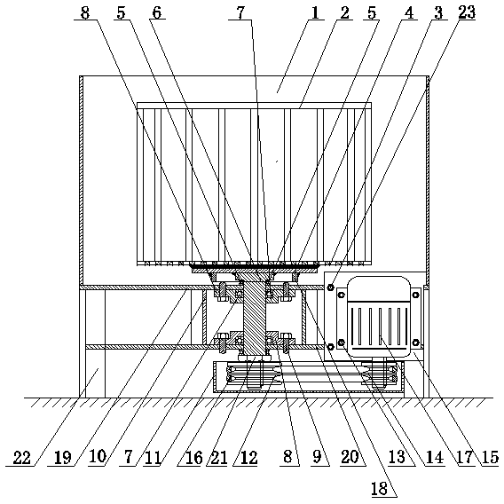
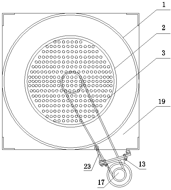
[0011] From figure 1 , figure 2 It can be seen from the figure that a centrifugal dezincification device for hot-dip galvanizing is characterized in that the centrifugal dezincification device for hot-dip galvanizing is mainly composed of a bracket, a protective cylinder 1, a dezincification basket 2, a lower bearing mounting plate 20, Main shaft 6, main nut 21, supporting plate 4, upper bearing seat 7, lower bearing seat 8, large belt pulley 12, small belt pulley 14, belt 16 and motor seat plate 15, motor 17, adjusting screw rod 23 form, and this support is made up of The uprights 22 and the top plate 19 that are uniformly distributed around the circumference and welded to the bottom plate are assembled and welded, and the uprights 22 are preferably four uprights that are evenly distributed around the circumference and the bottom is welded on the bottom plate. The uprights 22 of the support can be Angle steel is made, at the top of each vertical bar 22 welds the square top ...


PUM


Abstract

The invention relates to a centrifugal dezincification device used for hot galvanizing, which belongs to a hot galvanizing device and is characterized in that the hot galvanizing device mainly comprises a bracket, a protective barrel, a dezincification basket, a lower bearing mounting plate, a main shaft, a main nut, a supporting plate, an upper bearing seat, a lower bearing seat, a big belt pulley, a small belt pulley, a belt, a motor base plate, a motor and an adjusting screw rod, wherein a top plate is welded on the top of each vertical rod, a barrel wall is welded on the top plate to form the protective barrel, and the lower bearing mounting plate is horizontally welded between the middle sections of the vertical rods. The upper bearing seat is fixedly arranged on the bottom surface of a base plate of the protective barrel, the lower bearing seat is fixedly arranged on the lower bearing mounting plate, the main shaft is arranged in the upper bearing seat and the lower bearing seat in a penetrating mode, the disc-shaped supporting plate is welded on the upper end surface of a shaft shoulder of the main shaft, the grid-shaped dezincification basket is fixedly arranged on the supporting plate, the motor base plate and the motor are hinged on the base plate and the front right surface of the lower bearing mounting plate, the dezincification basket is driven to rotate by the driving of the belt, a workpiece is dezincified, the quality is high, and the consumption of zinc is low.

Description

technical field [0001] The invention belongs to a hot-dip galvanizing device, in particular to a hot-dip galvanizing dezincification device. Background technique [0002] At present, manufacturers of hot-dip galvanizing for small and screw parts usually use vibration dezincification to shake off the excess zinc on the surface of the workpiece. Zinc cannot be recycled, resulting in high zinc consumption and other defects. What's more, limited by the treatment process, the temperature of hot-dip galvanizing must be carried out at ≥ 480 ° C, and the life of the zinc pot is only 30-45 days, so it needs to be replaced or repaired; at the same time, due to the excessive thickness of the zinc layer, the The screw requires a negative machining allowance before plating and thread reprocessing after plating, which will destroy the integrity of the plating layer, seriously affect product quality, and affect the economic benefits of the enterprise. Contents of the invention [0003]...

Claims


Application Information

Patent Timeline
Patent Type & Authority Applications(China)
IPC IPC(8): C23C2/14C23C2/06
Inventor 彭仲平
Owner 安徽恒兴装备材料有限公司
Learn More