
Steel-fiber concrete combined bridge deck structure with reinforced joints and construction method of steel-fiber concrete combined bridge deck structure

A technology of fiber-reinforced concrete and fiber-reinforced concrete layers, applied in bridges, bridge parts, bridge materials, etc., can solve problems such as reducing the service life of bridge pavement layers, excessive local stress at joints, and reduction of concrete strength, etc., to achieve The effect of reducing the risk of weld fatigue cracking, improving local strength and stiffness, and preventing cracks

Active Publication Date: 2012-10-03
HUNAN UNIV
View PDF7 Cites 30 Cited by
  • Summary
  • Abstract
  • Description
  • Claims
  • Application Information

AI Technical Summary

Problems solved by technology

Most of the existing conventional bridge deck cement concrete pavement adopts the cast-in-place construction method. Because the bridge deck concrete is easy to shrink and crack, the existing cast-in-place construction technology cannot guarantee the construction quality, and the maintenance of large-scale cast-in-place concrete is very difficult. The strength of concrete will be greatly reduced due to insufficient maintenance, which will greatly reduce the service life of the bridge deck pavement
In addition, due to the long time of cast-in-place construction and the late opening of traffic, this will further affect the local traffic conditions and economic development
[0003] With the development and progress of material science, ultra-high performance fiber concrete has appeared in the field of bridge construction. Although the bridge deck structure obtained after fiber concrete construction has obvious advantages, the existing bridge deck pavement The overall cast-in-place construction method, there are many problems in pouring fiber concrete on the bridge deck through the integral cast-in-place construction method: for example, the construction period is long, the production efficiency is low, and the production cost is difficult to control; Steam curing of slabs is difficult; both steel bars and fiber concrete are vulnerable to the adverse effects of the environment, and are highly sensitive to the environment, especially the presence of a large number of chloride ions in the air in marine environments, which affects the corrosion resistance of steel bars and the durability of cast-in-place concrete It is a great threat, and it is difficult to guarantee the performance of the fiber concrete layer after pouring
[0004] In addition, prefabricated steel-fiber-reinforced concrete composite bridge deck structures have also begun to appear in the prior art, but the existing prefabricated composite deck structures have excessive local stress at the joints, cracks in the pavement layer, and bridge deck structure The durability and anti-fatigue performance are difficult to meet the use requirements and other defects

Method used


Image

  • Steel-fiber concrete combined bridge deck structure with reinforced joints and construction method of steel-fiber concrete combined bridge deck structure
  • Steel-fiber concrete combined bridge deck structure with reinforced joints and construction method of steel-fiber concrete combined bridge deck structure
  • Steel-fiber concrete combined bridge deck structure with reinforced joints and construction method of steel-fiber concrete combined bridge deck structure

Examples


Embodiment 1

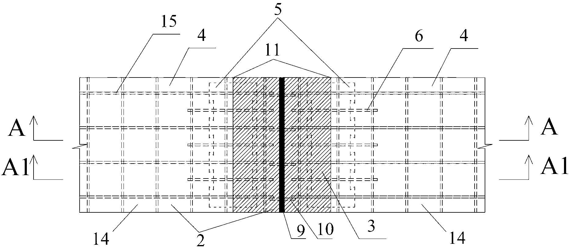
[0043] like Figure 2 ~ Figure 4 As shown, a steel-fiber concrete composite bridge deck structure with reinforced joints of the present invention is mainly composed of multiple steel plate-fiber concrete composite members 14 connected and assembled sequentially along the longitudinal direction of the bridge (in the figure only Two adjacent pieces are shown), the steel plate-fiber concrete composite member 14 includes the steel bridge deck 13 at the lower part and the prefabricated fiber concrete 4 poured on the steel bridge deck 13, the adjacent two steel plate-fiber concrete composite The abutment area of ​​the members 14 is provided with a reinforced joint type construction.

[0044] The reinforced joint structure in this embodiment includes cast-in-place fiber concrete parts 3 and steel plate reinforcement members 5 affixed to the steel bridge deck 13. The steel plate reinforcement members 5 are composed of prefabricated fiber concrete The cast-in-place fiber concrete part...

Embodiment 2

[0054] Such as Figure 6 ~ Figure 8 As shown, a steel-fiber concrete composite bridge deck structure with reinforced joints of the present invention is mainly composed of multiple steel plate-fiber concrete composite members 14 connected and assembled sequentially along the longitudinal direction of the bridge (in the figure only Two adjacent pieces are shown), the steel plate-fiber concrete composite member 14 includes the steel bridge deck 13 at the lower part and the prefabricated fiber concrete 4 poured on the steel bridge deck 13, the adjacent two steel plate-fiber concrete composite The abutment area of ​​the members 14 is provided with a reinforced joint type construction.

[0055] The reinforced joint structure in this embodiment includes cast-in-place fiber concrete parts 3 and steel plate reinforcement members 5 affixed to the steel bridge deck 13. The steel plate reinforcement members 5 are composed of prefabricated fiber concrete The cast-in-place fiber concrete p...


PUM


Abstract

The invention discloses a steel-fiber concrete combined bridge deck structure with reinforced joints. The steel-fiber concrete combined bridge deck structure is mainly formed by assembling a plurality of steel plate-fiber concrete combined components, each component comprises a steel bridge deck plate and a prefabricated fiber concrete element cast on the steel bridge deck plate, reinforced joint structures are arranged in butt joint regions of two adjacent components and comprise cast-in-situ concrete elements and steel plate reinforcing components, the steel plate reinforcing components are covered by prefabricated fiber concrete elements and cast-in-situ fiber concrete elements, the steel plate reinforcing components and the prefabricated concrete elements are connected in a tongue-and-groove engaging mode for forming an integral fiber concrete layer, and the adjacent steel bridge deck plates are welded into an integral steel bridge deck plate layer. A construction method provided by the invention comprises the following steps that the steel-fiber concrete combined components are firstly manufactured, then, the combination and split joint is carried out, and next, the repeated sequential assembly is carried out. The steel-fiber concrete combined bridge deck structure and the construction method have the advantages that the tensile strength and the rigidity of local parts of the combined bridge deck structure can be improved, the joint seam stress is reduced, and the generation of cracks of paving layers is prevented.

Description

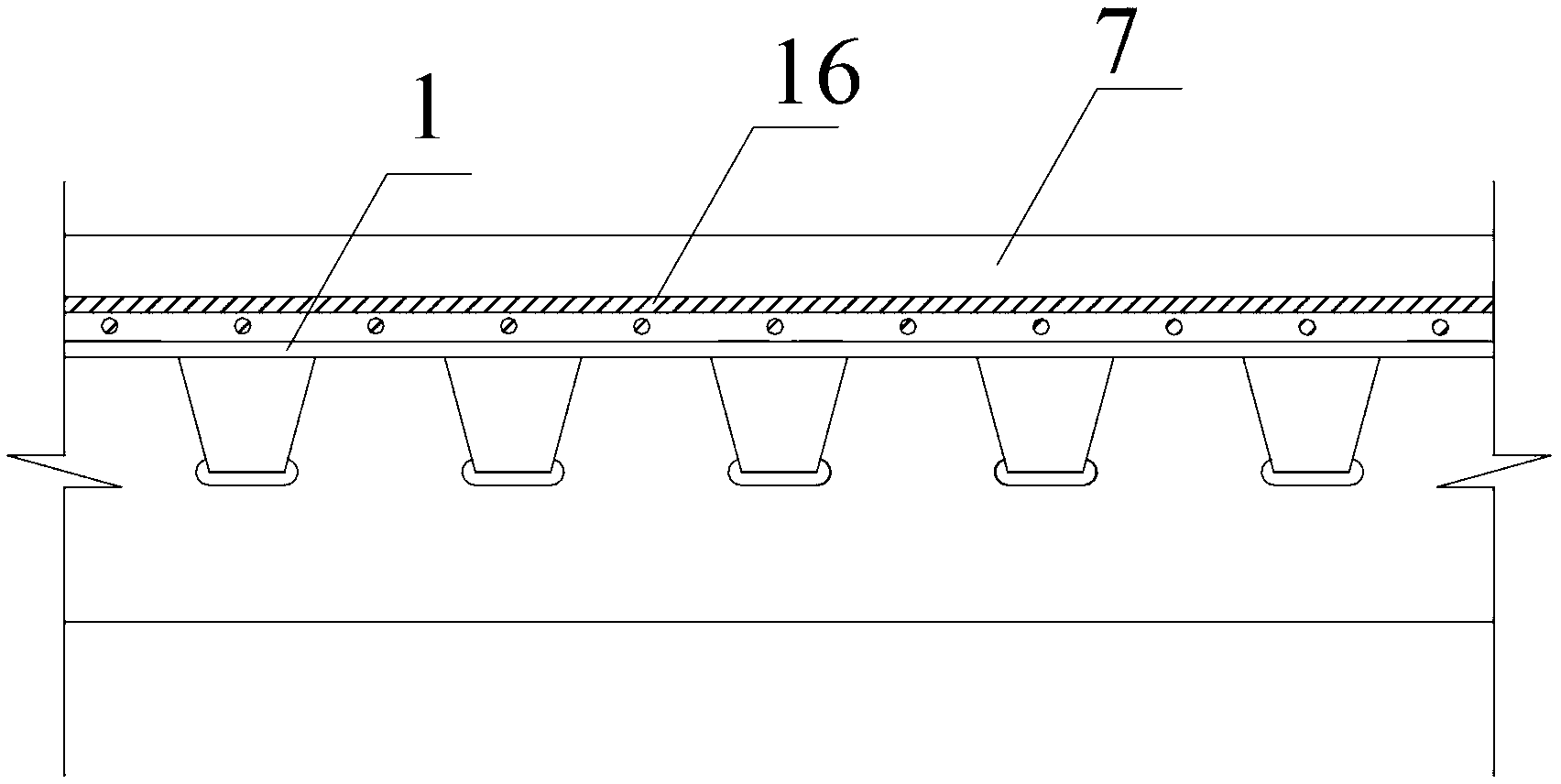
technical field [0001] The invention relates to a building detail of a bridge structure and its construction, in particular to a combined bridge deck structure and its construction method. Background technique [0002] The existing steel bridge cement concrete bridge deck pavement adopts the integral cast-in-place construction method, such as figure 1 As shown, after the construction is completed, a cast-in-place concrete pavement layer 7 is formed on the steel bridge deck layer 1, and reinforced steel bars 16 are prefabricated in the cast-in-place concrete pavement layer 7. Most of the existing conventional bridge deck cement concrete pavement adopts the cast-in-place construction method. Because the bridge deck concrete is easy to shrink and crack, the existing cast-in-place construction technology cannot guarantee the construction quality, and the maintenance of large-scale cast-in-place concrete is very difficult. The strength of concrete will be greatly reduced due to ...

Claims


Application Information

Patent Timeline
Patent Type & Authority Applications(China)
IPC IPC(8): E01D19/12E01D21/00E01D101/30
Inventor 邵旭东陈斌张喜刚曹君辉
Owner HUNAN UNIV
Learn More