Concrete sprayer

A technology of concrete spraying machine and spraying device, which is applied in the field of underground roadway reinforcement and concrete spraying machine, can solve the problems of underground roadway pollution, uneven batching, flying dust, etc., and achieve the effects of reducing labor intensity, eliminating replacement and reducing dust.

Inactive Publication Date: 2012-10-03
SHANXI FENXI MINING GRP
View PDF3 Cites 5 Cited by
  • Summary
  • Abstract
  • Description
  • Claims
  • Application Information

AI Technical Summary

Problems solved by technology

Otherwise, a large amount of dust will leak from the spraying device to the workplace, resulting in serious pollution of the underground roadway
[0004] With the existing concrete spraying equipment, the batching needs to be carried out in the construction site (underground roadway). The batching process is completely completed by manpower. Not only the labor intensity of the workers is high, but also the batching is uneven, the rebound is large, and the dust is also caused to fly.

Method used


Image

  • Concrete sprayer
  • Concrete sprayer
  • Concrete sprayer

Examples


Embodiment 1

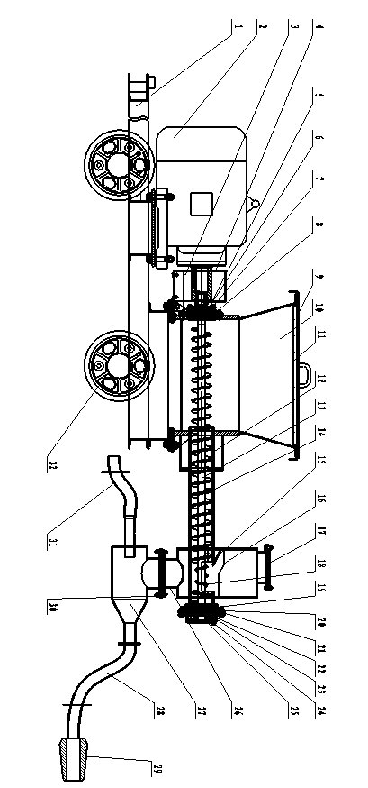
[0033] Embodiment one: figure 1 , figure 2 , image 3 , Figure 4 , Figure 5 As shown, this embodiment is composed of a supporting device, a spiral stirring device, a powder density changing chamber and a spraying device. The spiral stirring device is arranged on the support device, the spiral stirring device passes through the powder density changing chamber and is connected with the powder density changing chamber, the injection device is arranged under the powder density changing chamber and is connected with the powder density changing chamber, the powder The density changing bin is a closed cavity with high-pressure gas at one end. The top of the powder density changing bin is provided with an upper cover 17, the lower part of the powder density changing bin is provided with a feeding port, and the middle part of the powder density changing bin is provided with a stopper. feeding device.

[0034] The supporting device is composed of a steel beam 1 and two sets of w...

Embodiment 2

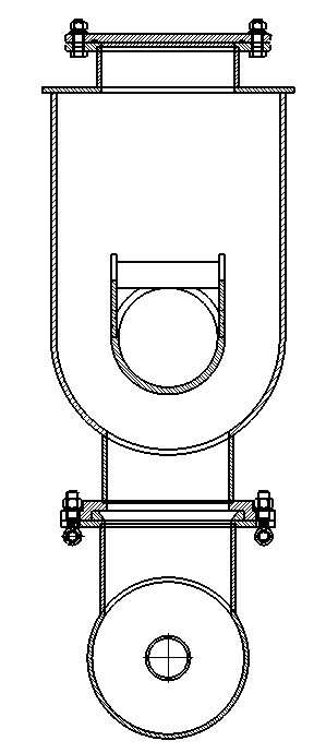
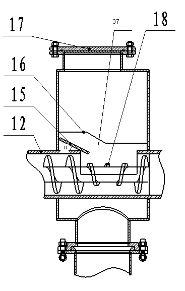
[0042] Embodiment two: Figure 8 , Figure 9 As shown, the shape of the powder density changing bin in this embodiment is rectangular, the top of the powder density changing bin is provided with an upper cover 17, and the bottom of the powder density changing bin is provided with a material outlet—feeding port, feeding tube 12 Pass through the powder density change bin, and the feeding tube 12 located in the inner cavity of the powder density change bin is provided with a discharge port 37, the discharge port 37 is a square port, and the left side of the discharge port 37 is provided with a stopper. The feeding device, the blocking device is composed of 4 plates, wherein two vertical plates 38, 39 are arranged parallel to the axis of the feeding tube and welded with the feeding tube, and the third vertical plate 40 is arranged perpendicular to the axis of the feeding tube and connected with the feeding tube axis. The feeding tube is welded, the bottom edge of the third vertical...

Embodiment 3

[0043] Embodiment 3: The feeding opening of the powder density changing bin of this embodiment is a square, and other structures are the same as those of Embodiment 2.


PUM


Abstract

The invention discloses a concrete sprayer which belongs to mine machinery and is mainly used for reinforcing underworkings. The concrete sprayer comprises a spiral stirring device, a material density change bin and a spraying device; the spiral stirring device penetrates through the material density change bin and is integrally welded with the material density change bin; and the spraying device is arranged below the material density change bin. The concrete sprayer is simple in structure, a rotor, upper and lower combination plates and a reinforcement plate are eliminated, and the replacement of the components are avoided; and meanwhile, raised dust is greatly reduced, and the labor intensity of workers is reduced.

Description

Technical field: [0001] The invention belongs to mining machinery and is mainly used for underground tunnel reinforcement. Specifically relates to a concrete sprayer. Background technique: [0002] Existing concrete spraying equipment includes a stirring device, a spraying device and a supporting device, and the spraying device includes a rotor, upper and lower joint plates and lining plates located on and below the rotor. [0003] In production practice, the service life of the upper and lower joint plates and lining plates is relatively short. Usually, when the workload reaches 40 tons, the upper and lower joint plates must be replaced; when the workload reaches 200 tons, the lining plates must be replaced. Otherwise, a large amount of dust will leak from the spraying device to the workplace, resulting in serious pollution of the underground roadway. [0004] With the existing concrete spraying equipment, the batching needs to be carried out in the construction site (und...

Claims


Application Information

Patent Timeline
IPC IPC(8): E21D11/10
Inventor 李立纲高炳王玉龙李海平王原际杨泽民李娜
Owner SHANXI FENXI MINING GRP
Why Eureka
Try Eureka