Brake disk of motor vehicle

A technology for brake discs and motor vehicles, applied in the field of brake discs, can solve the problems of easy deformation and scrapping of brake discs, influence of brake disc strength, high cost, etc., and achieve the effect of good ventilation and heat dissipation performance.

Inactive Publication Date: 2012-10-03
六安合众机械制造有限公司
View PDF5 Cites 5 Cited by
  • Summary
  • Abstract
  • Description
  • Claims
  • Application Information

AI Technical Summary

Problems solved by technology

[0005] For the current brake discs, the brake discs of automobiles are different from the brake discs of motorcycles. The thickness of the brake discs of automobiles is relatively large, and the cooling holes are opened along the radial direction of the brake disc. Although this type of brake disc has a good heat dissipation effect, it is difficult to manufacture. Larger, requiring higher cost casting molds; the motorcycle brake disc adopts a thin sheet structure, the cooling holes directly penetrate the brake disc, and are evenly distributed along the circumference, and in order to obtain the air flow through the cooling holes, the brake disc is usually made into a boss shape In this way, the strength of the brake disc will be greatly affected. In the process of frequent sudden braking, the brake disc is easily deformed and scrapped

Method used


Image

  • Brake disk of motor vehicle
  • Brake disk of motor vehicle
  • Brake disk of motor vehicle

Examples


Embodiment 1

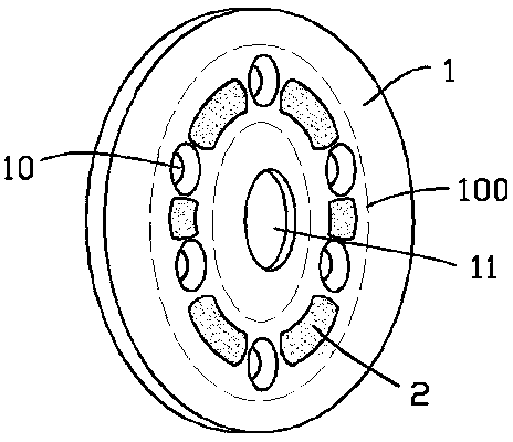
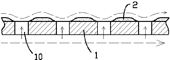
[0021] figure 1 Shown is the first embodiment of the present invention, wherein the motor vehicle brake disc includes a circular disc body 1, the center of the disc body 1 is provided with an axle fitting hole 11, and the disc body 1 is evenly provided with heat dissipation holes throughout the disc body 1 along the circumferential direction. Holes 10; on one side of the disc body 1, on the annular belt 100 formed by the heat dissipation holes 10, every other heat dissipation hole 10 is provided with a protuberance 2 with a streamlined surface; the annular belt 100, which can be approximately regarded as being surrounded by the common inner and outer tangent lines of the cooling holes 10; Note: figure 1 For the sake of clarity in the drawing, the annular zone 100 is drawn farther away from the enveloping line.

[0022] In this embodiment, the heat dissipation hole 10 is a circular hole, and the projected shape of the raised body 2 relative to the disk body 1 is adapted to the...

Embodiment 2

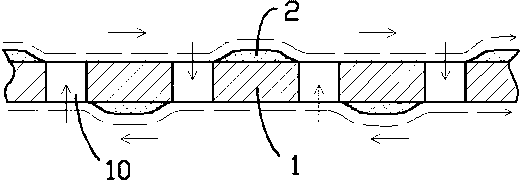
[0027] image 3 Shown is the second embodiment of the present invention. Since the first embodiment has been described in detail, only the expanded view of the brake disc is given in the second embodiment and explained. In the second embodiment, the machine The motor vehicle brake disc includes a circular disc body 1, and the disc body 1 is evenly provided with cooling holes 10 passing through the disc body along the circumferential direction; Above, every second heat dissipation hole 10 is provided with a protruding body 2 with a streamlined surface, and the positions of the protruding bodies 2 on both sides of the disc body 1 are arranged alternately.

[0028] The specific shapes of the heat dissipation holes 10 and the bumps 2 can be equivalent to those of the first embodiment.

[0029] The principle of Embodiment 2 is set forth below: when the brake disc rotates with the wheel at high speed, the airflow on the annular belts on both sides of the disc body 1 will flow throu...


PUM


Abstract

The invention provides a brake disk of a motor vehicle. The brake disk of the motor vehicle is applied to disk brake systems of motor vehicles of automobiles, motorcycles and the like and comprises a circular disk body, radiating holes penetrating through the disk body are evenly arranged on the disk body along the circumferential direction, and one rising body with the streamline surface is arranged on an annular zone formed by clustering of the radiating holes on one side of the disk body every other radiating hole. The brake disk of the motor vehicle has good ventilation radiating performance and is convenient to manufacture, low in cost and large in strength.

Description

[0001] technical field [0002] The invention relates to the field of motor vehicle accessories, in particular to a brake disc of a disc brake system of a motor vehicle, which includes a disc body and cooling holes. [0003] Background technique [0004] In automobiles and other motor vehicle systems, the brake mechanism generally adopts a disc brake mechanism. Its main structure is as follows: the brake disc is consolidated on the wheel shaft, and the edge of the brake disc is equipped with a hydraulic pressure device. When braking, it only needs to be moved by the hydraulic system The friction plates in the pressing device hold the brake disc tightly, and the brake disc decelerates rapidly under the action of friction. Because the huge kinetic energy of the car needs to be dissipated in a short time, and this kind of dissipation is basically reflected in the friction heat of the brake disc, so the brake disc will heat up rapidly during the braking process. Therefore, the...

Claims


Application Information

Patent Timeline
Patent Type & Authority Applications(China)
IPC IPC(8): F16D65/12F16D65/847
Inventor 马根昌
Owner 六安合众机械制造有限公司
Why Eureka
Try Eureka