Application method of polling-method-based multitask scheduling and software timer in air source heat pump water heater
An air source heat pump and its realization method technology, which is applied to fluid heaters, lighting and heating equipment, etc., can solve the problems of not meeting the requirements, the accuracy of the timer is not high, and the task execution time cannot be executed accurately, etc., to achieve Improve timing efficiency and strong scalability
- Summary
- Abstract
- Description
- Claims
- Application Information
AI Technical Summary
Problems solved by technology
Method used
Image

Examples
Embodiment Construction
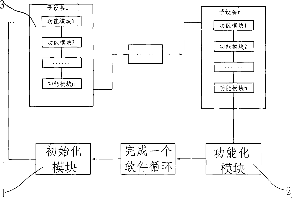
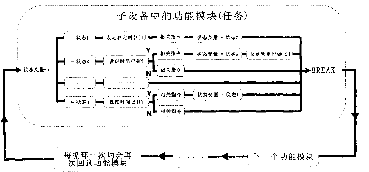
[0011] See Figure 1 to Figure 3 Shown: the present invention comprises initialization module 1, function module 2, sub-equipment 3, initialization module 1 is connected with function module 2, at least one sub-equipment 3, and its implementation method is: the control of each independent sub-equipment 3 is controlled by Controlled by the software control module, each functional module 2 adopts a state machine method, and each time it runs to a certain module, if the current state of the module is not completed, then switch to another module until the next switch back to this module, And the current state is completed before entering the next state to continue running.
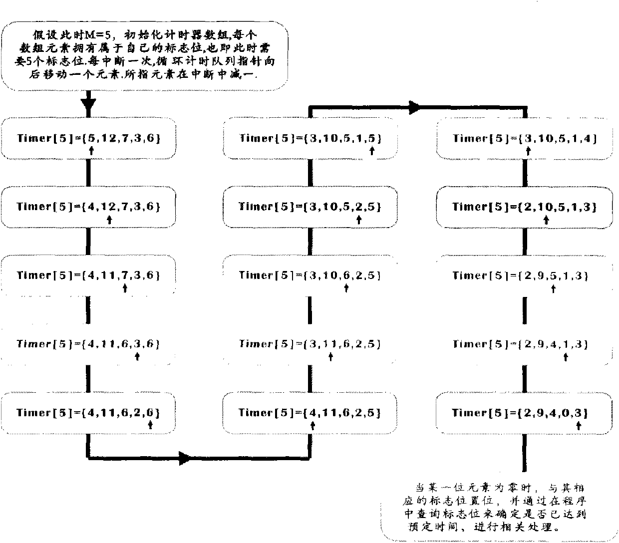
[0012] The software loop is a single loop queue timer algorithm.
[0013] The working modes of the air source heat pump air conditioning system include: cooling mode, heat pump mode, air conditioning heat pump mode, slippery mode and idle mode.
[0014] The following table shows the control output of various...
PUM
 Abstract
Description
Claims
Application Information
PatSnap Eureka turns technology decisions into work you can execute. Powered by our Innovation Knowledge Graph, it runs expert workflows across engineering, life sciences, materials and intellectual property. Get your review-ready output in minutes.


