
Method and system for realizing network topology relationship of time synchronization device

A technology of a time synchronization device and a network topology is applied to the realization of the network topology relationship of the time synchronization device, and the realization of the network topology relationship of the time synchronization device in the system field, so as to achieve the effect of improving the time synchronization efficiency.

Active Publication Date: 2020-08-14
STATE GRID JIANGSU ELECTRIC POWER CO ELECTRIC POWER RES INST +5
View PDF5 Cites 0 Cited by
  • Summary
  • Abstract
  • Description
  • Claims
  • Application Information

AI Technical Summary

Problems solved by technology

[0004] The purpose of the present invention is to overcome the deficiencies in the prior art, provide a method and system for realizing the network topology relationship of a time synchronization device, and solve the problem of automatic generation of time synchronization network topology of substation timing equipment and timed equipment

Method used


Image

  • Method and system for realizing network topology relationship of time synchronization device
  • Method and system for realizing network topology relationship of time synchronization device
  • Method and system for realizing network topology relationship of time synchronization device

Examples


Embodiment 1

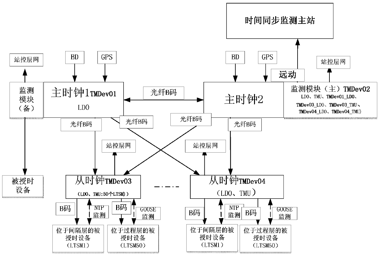
[0055] A method for realizing the network topology relationship of a time synchronization device, see figure 1 As shown, including master clock 1 and master clock 2 with monitoring function, and multiple slave clocks;

[0056]According to the relevant standards in the actual substation, two master clocks (respectively recorded as master clock 1 and master clock 2) must be equipped. Master clock 1 and master clock 2 can use the "four unification" type II clocks in the prior art, with time synchronization Monitoring function, the master clock 1 and the master clock 2 are mutually backup, and the master clock 2 is used as the main monitoring clock. The monitoring module of the master clock 2 collects the clock information and sends it to the time synchronization monitoring master station through IEC61850.

[0057] Master clock 1 and master clock 2 receive clock signals through the Beidou satellite navigation system (BD) and the global positioning system (GPS);

[0058] Interacti...

Embodiment 2

[0098] Based on the same inventive concept as the above-mentioned method, a network topology relationship realization system of a time synchronization device of the present invention, the time synchronization device includes a master clock 1, a master clock 2 and a plurality of slave clocks, and the master clock 1 is connected with each slave clock to Monitor each slave clock, the master clock 2 is connected to the master clock 1 and the two are mutually active and standby, and each slave clock is connected to multiple timed devices;

[0099] The system includes a time synchronization device information model modeling module and a time synchronization device information model analysis module;

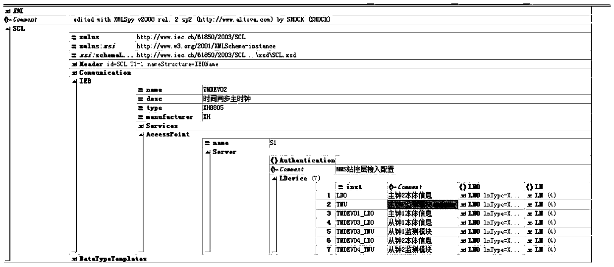
[0100] The time synchronization device information model modeling module adopts the IEC61850 hierarchical modeling method to construct the time synchronization device information model. The time synchronization device information model includes intelligent devices, logic devices and logi...


PUM


Abstract

The invention relates to a method and a system for realizing network topological relation of a time synchronization device, and the method comprises the steps: S1, employing an IEC61850 hierarchical modeling mode to construct a time synchronization device information model, and defining an intelligent device, logic equipment, and a logic node in the time synchronization device; and S2, analyzing the time synchronization device information model according to an IEC61850 rule, and obtaining a network topological relation. According to the invention, automatic network topology can be realized through hierarchical modeling of the time synchronization device IEC61850. Therefore, the connection relation between each clock and the time-service equipment can be clearly seen, so that the time service can be carried out according to the network topology subsequently, the time service efficiency is improved, and the problem of automatic generation of the time-service network topology by the timeservice equipment of the transformer substation and the time-service equipment is solved.

Description

technical field [0001] The invention relates to the technical field of electric power system automation, in particular to a method for realizing a network topology relationship of a time synchronization device, and also to a system for realizing the network topology relationship of a time synchronization device. Background technique [0002] With the development of smart substations, the substation time synchronization system is playing an increasingly important role. Substation time synchronization system is an important basic condition for power system operation control and fault analysis. Its core function is to provide timing services for power grid operating equipment and provide a unified time reference for power grid data collection and fault analysis. [0003] However, the current time synchronization system only has a one-way time service function, and lacks corresponding management functions and intuitive visual display. The connection relationship between the time...

Claims


Application Information

Patent Timeline
Patent Type & Authority Patents(China)
IPC IPC(8): H04J3/06H04L12/24H04L12/26
Inventor 周琦彭志强郑明忠徐春雷霍雪松张琦兵卜强生曾飞樊海锋李虎成夏杰董可为曹伟杰张刘冬张潼周怡君全思平韩禹许颖文刘丽君
Owner STATE GRID JIANGSU ELECTRIC POWER CO ELECTRIC POWER RES INST
Features
  • Generate Ideas
  • Intellectual Property
  • Life Sciences
  • Materials
  • Tech Scout
  • Unparalleled Data Quality
  • Higher Quality Content
  • 60% Fewer Hallucinations
Learn More