Variable valve gear for internal combustion engine

An internal combustion engine, variable technology, applied in valve devices, valve drive devices, mechanical equipment, etc., can solve problems such as the inability of the threaded part to be compactly designed, the responsiveness of the variable valve device is deteriorated, and the abnormal wear between parts, etc., to achieve compact size. , The effect of preventing abnormal wear and inhibiting the increase of friction

Inactive Publication Date: 2013-07-31
MITSUBISHI MOTORS CORP
View PDF2 Cites 0 Cited by
  • Summary
  • Abstract
  • Description
  • Claims
  • Application Information

AI Technical Summary

Problems solved by technology

In addition, since it is a cantilever structure and tends to concentrate stress, it is necessary to increase the strength near the threaded part, and the problem of compact design cannot be achieved.
[0011] The generation of this kind of friction not only deteriorates the responsiveness of the variable valve device, but also increases the friction of the engine as a whole, which increases fuel consumption and further causes abnormal wear between parts.

Method used


Image

  • Variable valve gear for internal combustion engine
  • Variable valve gear for internal combustion engine
  • Variable valve gear for internal combustion engine

Examples


Embodiment Construction

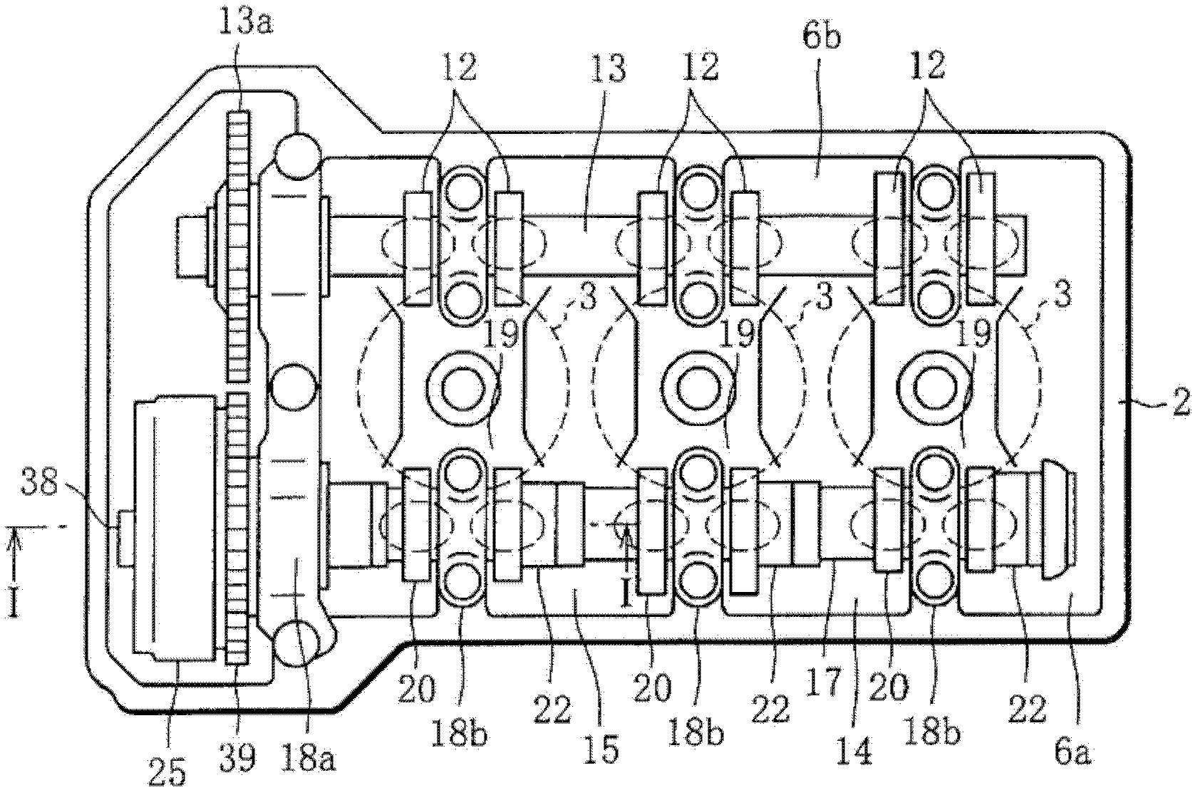
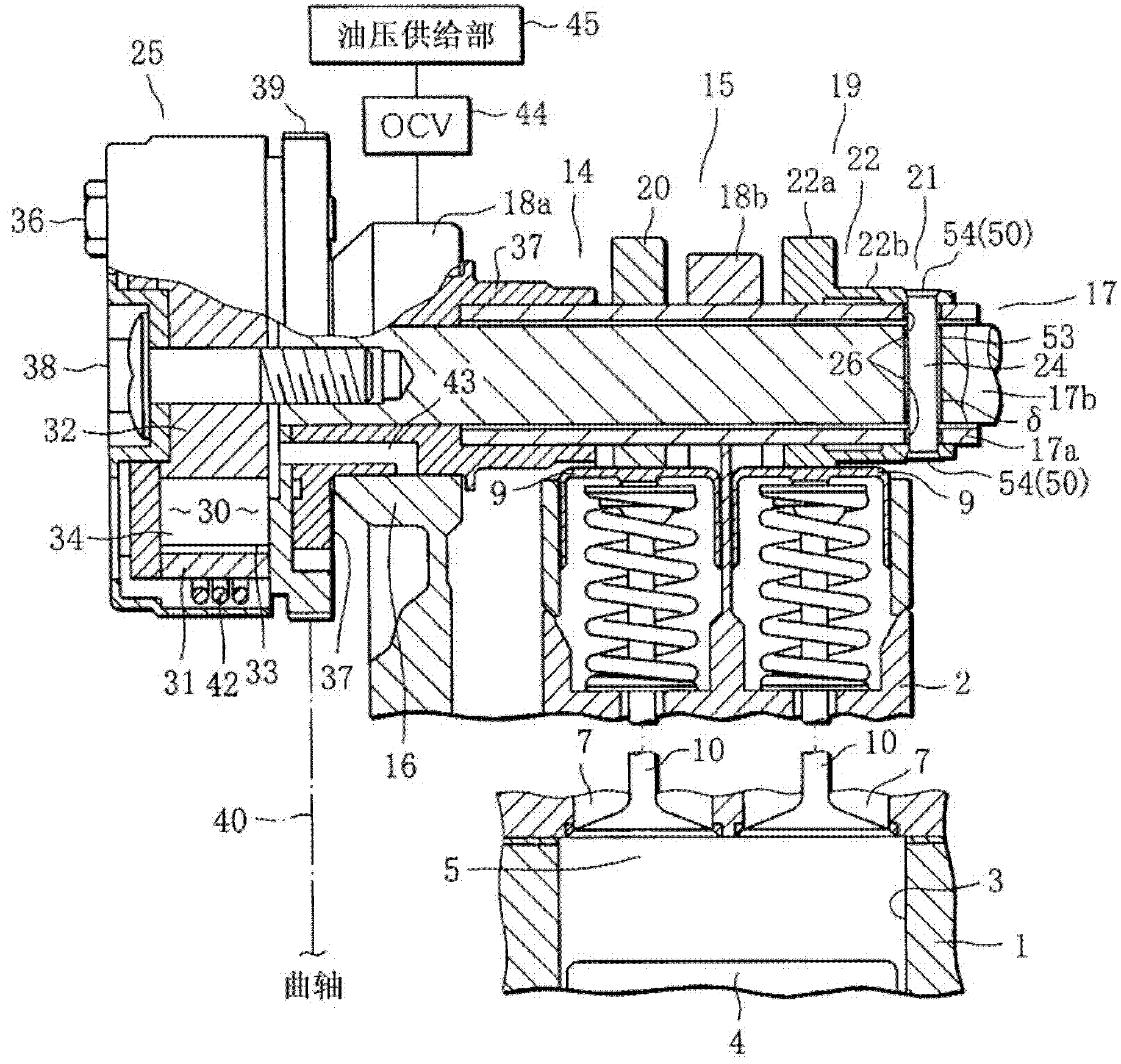
[0066] Below, according to Figure 1 to Figure 5 The present invention will be described with reference to the first embodiment shown.

[0067] figure 1 A plane representing an internal combustion engine, such as a three-cylinder (multiple cylinders) reciprocating engine (hereinafter simply referred to as an engine), figure 2 means along figure 1 In the cross section of line II in the figure, 1 in the figure is the cylinder block of the engine, and 2 is the cylinder head mounted on the head of the cylinder block 1.

[0068] Among them, such as figure 1 and figure 2 As shown, three cylinders 3 (only partial cylinders are shown) are formed on the cylinder block 1 along the front-rear direction of the engine. Each of these cylinders 3 accommodates reciprocating pistons 4 (only figure 2 icon).

[0069] Combustion chambers 5 corresponding to the respective cylinders 3 are formed on the lower surface of the cylinder head 2 . A pair of intake ports 7 (two) for intake and a...


PUM


Abstract

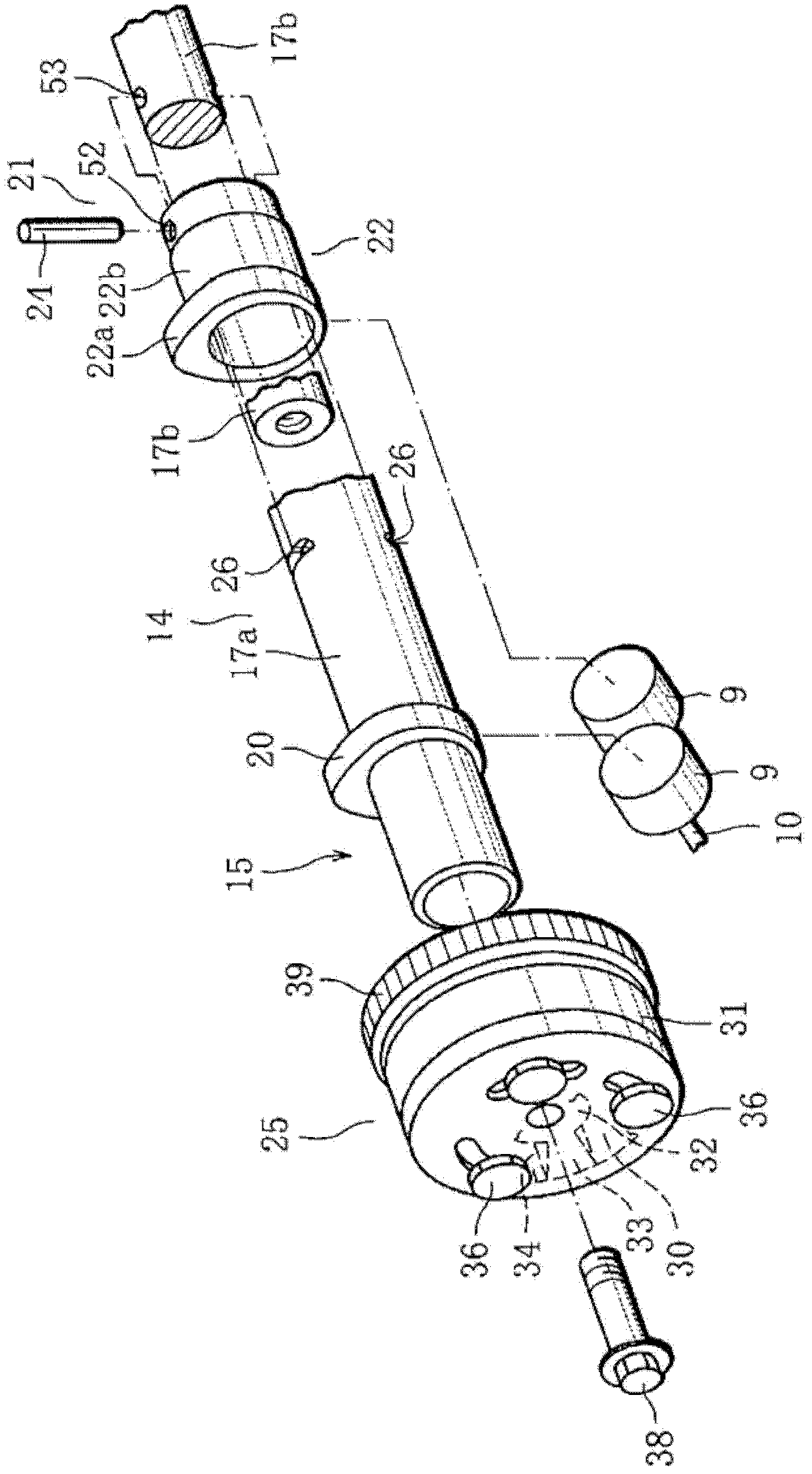
A variable valve device of the invention has a structure in which, as connecting means for connecting a movable cam 22 located in an outer periphery of an outer camshaft 17a and an inner camshaft 17b located inside the outer camshaft 17a, there are provided a pin-like member 24 that is movably inserted so as to penetrate the movable cam 22, the outer camshaft 17a and the inner camshaft 17b along a diametrical direction of a shaft member 17 that is formed by turnably encasing the inner camshaft 17b in the outer camshaft 17a, and an escape-preventing portion 50 disposed in the end portion of the pin-like member 24. The movable cam 22 and the inner camshaft 17b are thus connected together while preventing large press-fit load and axial force from acting on components.

Description

technical field [0001] The present invention relates to a variable valve device for an internal combustion engine in which the phase of a movable cam is variable based on a reference cam. Background technique [0002] In a reciprocating engine (internal combustion engine) mounted on an automobile, a variable valve device is mounted on the cylinder head in order to cope with engine exhaust gas and improve pumping loss. [0003] For this variable valve device, there is the following structure: a rotatable inner camshaft is accommodated in an outer camshaft formed by a pipe member, and it is made into a shaft member driven by the output of the crankshaft of the engine. There is a fixed reference cam and a movable cam that can rotate around the axis of the shaft, and the pin-shaped component that is inserted between the movable cam and the inner camshaft in the radial direction from the shaft allows the outer camshaft and the inner camshaft to The relative displacement between ...

Claims


Application Information

Patent Timeline
Patent Type & Authority Patents(China)
IPC IPC(8): F01L1/34F01L1/04
CPCF01L2820/041F01L2001/0537F01L2001/34489F01L1/0532F01L1/143F01L2001/0473F01L2001/34483F01L1/022F01L1/3442F01L2001/34486F01L2250/02F01L1/34F01L1/04
Inventor 松永礼俊吉贺大辅田中克博村田真一
Owner MITSUBISHI MOTORS CORP
Why Eureka
Try Eureka