Wind turbine
A technology of wind power equipment and windmills, which is applied in the direction of mechanical equipment, wind power generation, wind power motor combination, etc., can solve problems such as large investment risks, and achieve the effect of improving electrical connections
- Summary
- Abstract
- Description
- Claims
- Application Information
AI Technical Summary
Problems solved by technology
Method used
Image

Examples
Embodiment Construction
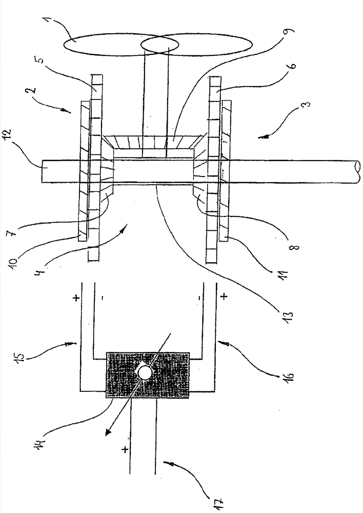
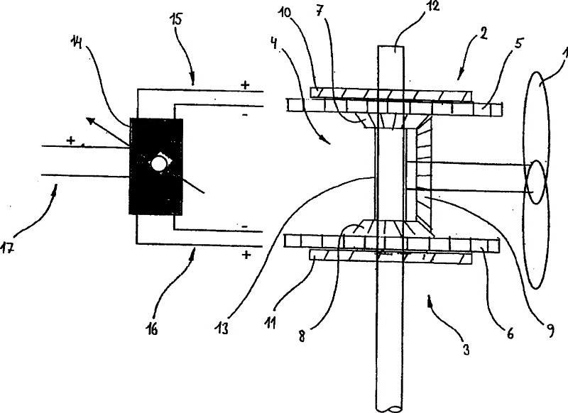
[0012] The drawing is a schematic illustration of a wind power plant according to the invention, which comprises a windmill 1 and two generators 2 , 3 which are designed as ring generators and are mechanically coupled to one another via a differential 4 . The counter-rotating rotors 5 , 6 of the generators 2 , 3 are each connected to a shaft wheel 7 , 8 of the differential 4 , wherein the windmill 1 is arranged on a compensating gear 9 of the differential 4 . The stators 10, 11 of the generators 2, 3 are connected through a hollow shaft 12 to form a thrust bearing, and the differential case 13 of the differential 4 is rotatably mounted on the thrust bearing. Each generator 2 , 3 has an axis of rotation oriented at right angles to the axis of rotation of windmill 1 embodied as a leeward rotor. The generators 2 , 3 are electrically connected to each other through a collector regulator 14 . In order to establish this connection, it is necessary to pass (not shown) generator elec...
PUM
 Abstract
Description
Claims
Application Information