Power transmission device

A technology of power transmission device and power transmission mechanism, applied in the direction of transmission device, transmission belt, transmission element or rope or cable for pulley, etc., can solve problems such as poor durability, and achieve the effect of easy manufacture and improved durability

Active Publication Date: 2012-10-03
YKK CORP
View PDF6 Cites 3 Cited by
  • Summary
  • Abstract
  • Description
  • Claims
  • Application Information

AI Technical Summary

Problems solved by technology

In order to enable such a ball chain to transmit large power, the bead-shaped member and the link member are made of metal, so that it can be used in a power transmission device that drives the roller group that constitutes the article conveyance path instead of the above-mentioned roller chain. In the medium time, the above-mentioned risks and costs are reduced, and the maintenance is also easy, but the durability is poor

Method used


Image

  • Power transmission device
  • Power transmission device
  • Power transmission device

Examples


Embodiment Construction

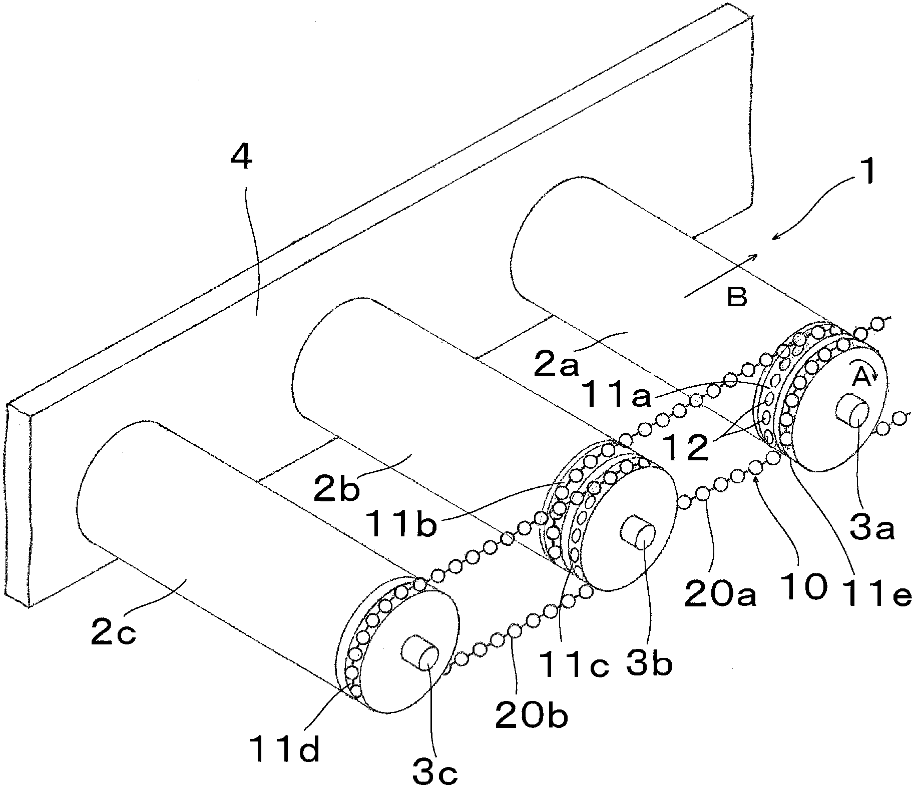
[0017] Hereinafter, preferred embodiments of the present invention will be described with reference to the drawings. figure 1 It is a perspective view schematically showing a part of a conveyor 1 incorporating a power transmission device 10 according to an embodiment of the present invention. Conveyor 1 comprises: many cylindrical roller bodies 2a, 2b, 2c (in figure 1 For the convenience of illustration, only the three rollers are shown with a larger interval than usual), which are arranged in a manner that their respective axes are parallel to each other; the left and right side plates 4 (in figure 1 Only one side plate is shown in the figure), which supports both ends of the rotating shafts 3a, 3b, 3c of the roller bodies 2a, 2b, 2c to be rotatable by means of bearings (not shown); the power transmission device 10, which It is for transmitting the rotational power of the roller body 2a rotationally driven by the motor not shown to the roller bodies 2b and 2c. The roller bo...


PUM


Abstract

Provided is a power transmission device using a metal ball chain having high durability. The power transmission device is provided with a first pulley (11a), a second pulley (11b), and a ball chain (20) wound around the first pulley (11a) and the second pulley (11b). The ball chain (20) has a plurality of metal ball members (21) having a hollow spherical shape, and metal link members (23), each of which couples two adjacent ball members (21) to each other. The metal ball members (21) are provided with two link holes (22) for connecting with the link memebers (23) at two sides of a diameter direction. The link memebers (23) are provided with connecting rods (24) which is straight-line rodlike and can enter and exit with respect to the ball members (21) through the link hols (22), and anti-fallout ends (25) which is disposed on two ends of the connecting rods (24) and inside the ball memebers (21) and have a size making the connecting rods (24) be unable to pass through the link holes (22). The first and second pulleys (11a, 11b) have, in the outer circumferential direction, a plurality of ball engagement grooves (12) in which the ball members (11) are engaged. The pitch between the two adjacent ball engagement grooves (12) in the circumferential direction is set to be smaller than the pitch between the two adjacent ball members (21) in the ball chain (20).

Description

technical field [0001] The invention relates to a power transmission device, in particular to a power transmission device which utilizes ball chains to transmit power between pulleys. Background technique [0002] A power transmission device that transmits power by winding an endless chain or the like between pulleys is generally used, for example, in a conveyor for conveying articles. In this conveyor, a plurality of rollers are arranged so that their axes are parallel to each other, and an article conveyance path extending in a direction perpendicular to the axis is formed above the group of rollers. Moreover, two or more pulleys are provided on each roller body, and chains are wound on the pulleys of two adjacent roller bodies in the direction of the article conveying path, and the rotation of one or more roller bodies driven by a motor The power is transmitted to other rollers through the chain, so that the item moves on the item conveying path. As the above-mentioned ...

Claims


Application Information

Patent Timeline
Patent Type & Authority Applications(China)
IPC IPC(8): F16H7/06F16G13/12
CPCF16G1/28F16G9/00F16H7/06F16G13/18
Inventor 出村良广
Owner YKK CORP
Why Eureka
Try Eureka