Coil form for mounting on a magnet core, magnet core for reluctance resolvers, and method of manufacture

A coil frame and magnetic core technology, which is applied to the shape/style/structure of magnetic circuits, electromechanical devices, and winding insulation, can solve problems such as unfavorable welding processing of components, and achieve the effect of high retention force

Active Publication Date: 2012-10-03
TYCO ELECTRONICS BELGIUM EC
View PDF5 Cites 8 Cited by
  • Summary
  • Abstract
  • Description
  • Claims
  • Application Information

AI Technical Summary

Problems solved by technology

[0010] Another disadvantage of the known gripping hooks 214 is that the parts interlock

Method used


Image

  • Coil form for mounting on a magnet core, magnet core for reluctance resolvers, and method of manufacture
  • Coil form for mounting on a magnet core, magnet core for reluctance resolvers, and method of manufacture
  • Coil form for mounting on a magnet core, magnet core for reluctance resolvers, and method of manufacture

Examples


Example Embodiment

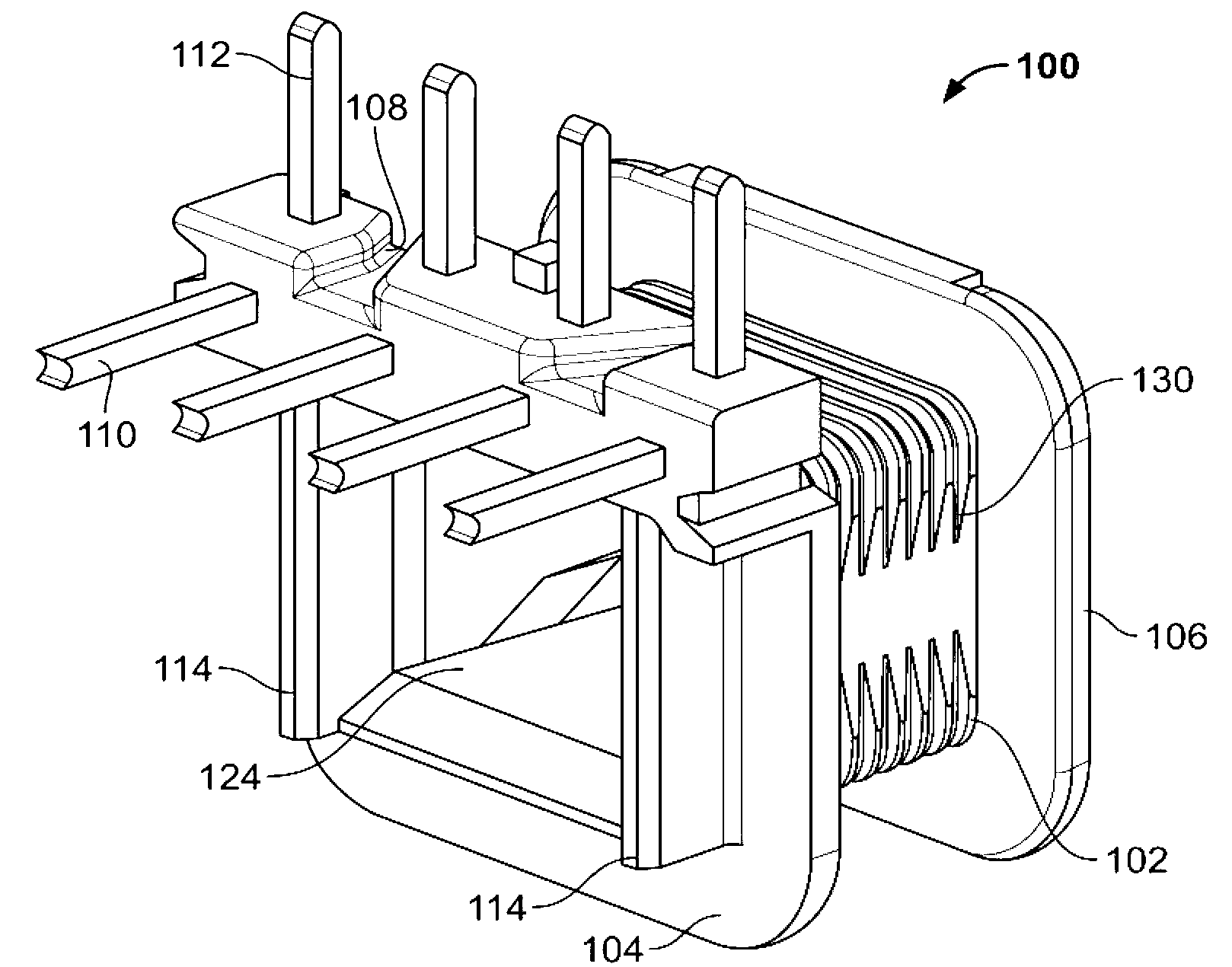
[0059] In the following, advantageous embodiments of the present invention are described in more detail with reference to the accompanying drawings. In this regard, it should be noted that although the magnetic core of the stator that can be used as a reluctance resolver is always presented below, the present invention can naturally be applied to any type of rotating electrical equipment. This means that the fixing type of the coil former according to the invention can also be used for electric machines and motors both on the stator core and on the rotor core.

[0060] Further, the present invention is not limited to these embodiments: in which the teeth of the magnetic core protrude inwardly from the ring yoke toward the central axis; the magnetic core teeth arranged on the outer periphery of the magnetic core can also be arranged in an equivalent and similar manner accordingly There is a coil former according to the invention.

[0061] Finally, the bobbin according to the presen...


PUM


Abstract

The present invention relates to a coil form (100) for mounting on a magnet core (118) for a rotating electrical machine or a resolver and to a corresponding magnet core. The present invention further relates to a magneto-electric angle sensor, in particular a reluctance resolver, the stator of which is constructed by the principles according to the invention. The coil form has a winding form (102) for applying a winding, the winding form (102) comprising a recess (124) for receiving a tooth (116) of the magnet core (118), at least one holding rib (114) being integrally formed and in cooperation with a holding structure (120) of the magnet core (118) fixing the coil form to the tooth.; The magnet core comprises a plurality of lamellae (136) manufactured from sheet metal, which are layered on top of one another in a plane-parallel manner and interconnected, every two lamellae which lie on top of one another being rotated through an offset angle relative to one another to form the holding structure (120).

Description

technical field [0001] The invention relates to a bobbin for mounting on a magnetic core of a rotating electric machine and to a corresponding magnetic core. The invention further relates to a magnetoelectric angle sensor, in particular a reluctance resolver, the stator of which is constructed according to the principles of the invention. Finally, the invention relates to a manufacturing method for manufacturing a reluctance solver of this type. Background technique [0002] A reluctance resolver of this type has an at least partially soft magnetically rotationally symmetric stator and an at least partially softly magnetically rotationally symmetric rotor, the stator and rotor being positioned opposite each other so as to form a gap. The reluctance in this gap varies periodically based on the shape of the rotor which changes around the circumference. [0003] The angle sensor comprises a magnetic flux transmitter which is arranged on the stator and generates a predetermine...

Claims


Application Information

Patent Timeline
IPC IPC(8): H02K3/52H02K3/32H02K24/00
CPCH02K24/00H02K3/522H02K1/146H02K2203/12Y10T29/49009H02K3/32H02K3/52
Inventor S.范尼曼T.奥克特J.福斯特里特J.范考温伯格H.米斯
Owner TYCO ELECTRONICS BELGIUM EC
Why Eureka
Try Eureka