Inductance parameter identification method of synchronous motor and implementation system thereof

A technology for synchronous motors and inductance parameters, which is applied in the estimation/correction of motor parameters, control systems, inductance measurement, etc., and can solve problems such as detection and calculation difficulties

Active Publication Date: 2012-10-03
SHENZHEN INVT ELECTRIC
View PDF4 Cites 47 Cited by
  • Summary
  • Abstract
  • Description
  • Claims
  • Application Information

AI Technical Summary

Problems solved by technology

[0011] For the DC inductance L of the synchronous motor in the above-mentioned prior art d and the quadrature axis inductance L q For the shortcomings of difficult detection and calculation, the present invention provides a synchronous motor inductance parameter identification method and its implementation system, which applies a group of three-phase balanced high-frequency voltage or current signals to the synchronous motor, and samples the feedback of the synchronous motor. The d-axis inductance L of the synchronous motor is calculated according to the amplitude of the positive sequence component and the negative sequence component of the feedback current or voltage d and q-axis inductance L q

Method used


Image

  • Inductance parameter identification method of synchronous motor and implementation system thereof
  • Inductance parameter identification method of synchronous motor and implementation system thereof
  • Inductance parameter identification method of synchronous motor and implementation system thereof

Examples


Embodiment Construction

[0046] This embodiment is a preferred embodiment of the present invention, and other principles and basic structures that are the same as or similar to those of this embodiment fall within the protection scope of the present invention.

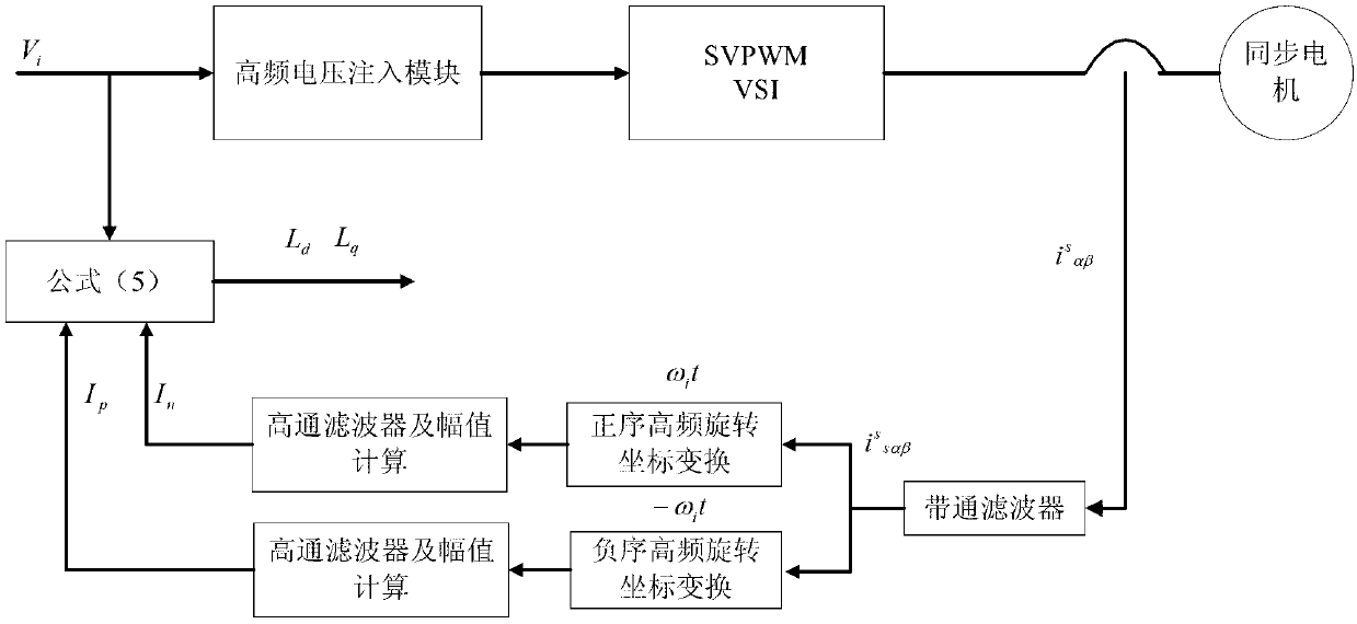
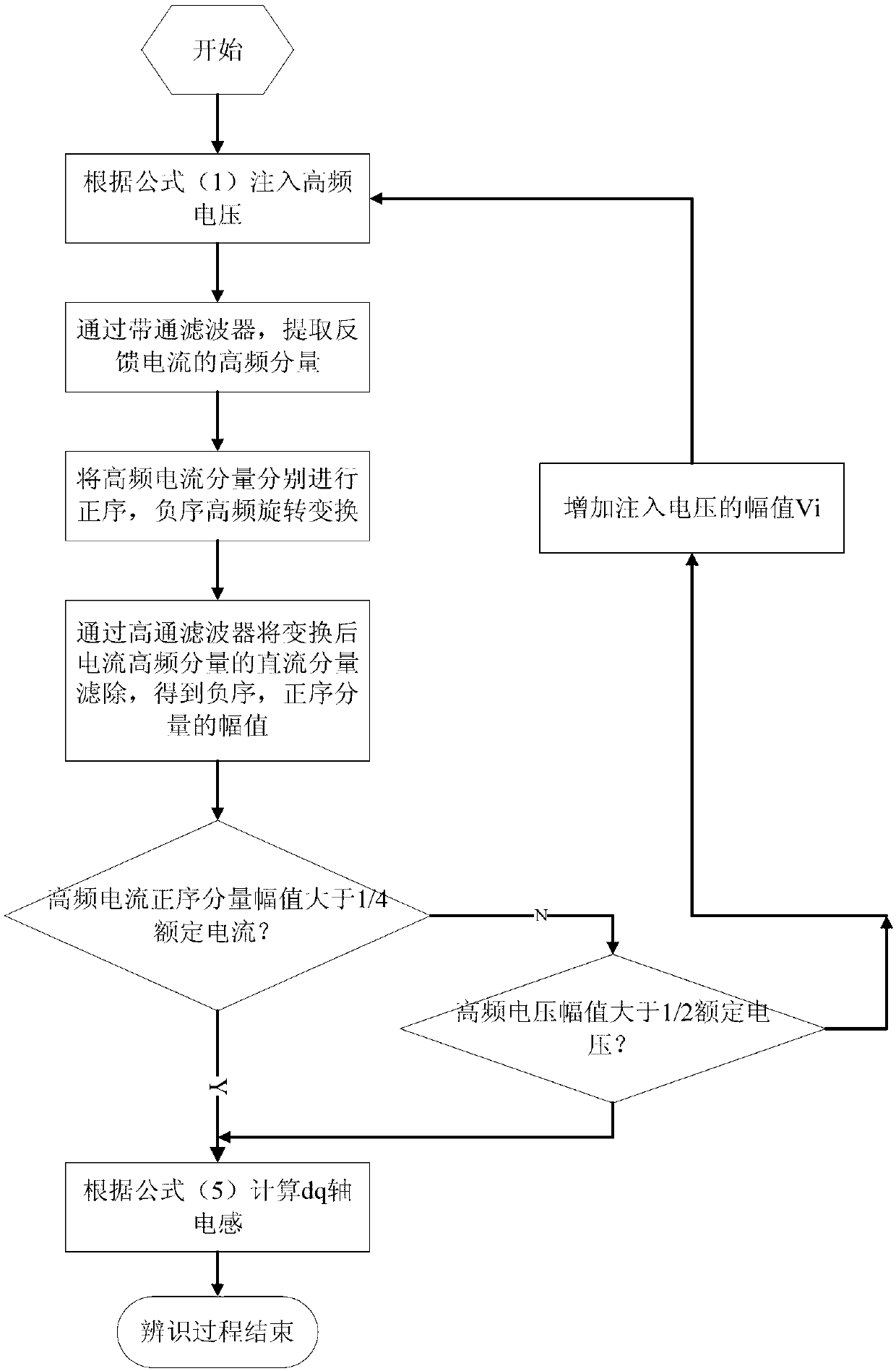
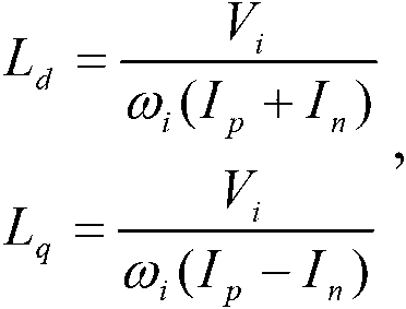
[0047] The main purpose of the present invention is to inject a set of three-phase balanced high-frequency voltage or current signals into a static coordinate system α-β coordinate system arbitrarily selected in the synchronous motor to obtain the feedback high-frequency current or voltage of the synchronous motor and the injected voltage or The positive sequence component amplitude and the negative sequence component amplitude with the same current frequency are calculated according to the positive sequence component amplitude and negative sequence component amplitude of the feedback high-frequency current or voltage to obtain the d-axis inductance L of the synchronous motor d And q-axis inductance L q . In the present invention, when injecting a...


PUM


Abstract

An inductance parameter identification method of a synchronous motor and an implementation system thereof are provided. The method comprises: applying a three-phase balance high frequency voltage or current signal to the synchronous motor; sampling a feedback high frequency current or voltage of the synchronous motor; extracting positive sequence and negative sequence component amplitude of the feedback high frequency current or voltage which has the same frequency of the injecting voltage or current; and calculating to get d-axis inductance Ld and q-axis inductance Lq of the synchronous motor. Identification of the d-axis inductance and q-axis inductance of the synchronous motor can be implemented more accurately on a general inverter on the basis of non-increase of hardware cost. The method and system have the following advantages of implementing easily, not high demand for the motor feedback current sampling accuracy, and controlling easily for the frequency and amplitude of the high frequency voltage signal injected into the motor, and identifying to get the d-axis inductance and q-axis inductance of the motor directly no matter the motor shaft is in a free state, or in a hold tight stage, which do not affect accuracy of identification.

Description

Technical field [0001] The invention discloses an inductance parameter identification method and its realization system, in particular to a synchronous motor inductance parameter identification method and its realization system. Background technique [0002] Permanent magnet synchronous motors have the advantages of high power density, low loss, high efficiency, high power factor, suitable for direct drive, etc., and are more and more widely used in the field of electric drives. In the early days, synchronous motors usually used vector control with encoder feedback or open-loop V / F control, and their application areas were greatly restricted. At present, the speed sensorless vector control technology of synchronous motors has been mastered by a few inverter manufacturers and used in plastics, machinery, oil fields, fans, pumps and other fields. The speed sensorless vector control usually adopts the orientation strategy of the rotor flux (that is, the permanent magnet flux), and ...

Claims


Application Information

Patent Timeline
Patent Type & Authority Applications(China)
IPC IPC(8): H02P21/14
CPCH02P21/14G01R31/34G01R27/2611H02P23/14H02P2203/11
Inventor 王玉雷徐铁柱
Owner SHENZHEN INVT ELECTRIC
Why Eureka
Try Eureka