Fuel injector with perturbation spray nozzle

A technology of fuel injectors and nozzles, which is applied in the direction of engine components, fuel injection devices, machines/engines, etc., to achieve the effects of uniform oil and gas mixing, huge market space, and high atomization intensity

Inactive Publication Date: 2012-10-10
中国船舶重工集团公司第七〇三研究所
View PDF6 Cites 2 Cited by
  • Summary
  • Abstract
  • Description
  • Claims
  • Application Information

AI Technical Summary

Problems solved by technology

The degree of atomization of fuel oil in internal combustion engines has a great impact on the economy and emissions of the engine. The methods to increase the atomization intensity mainly include increasing the injection pressure and organizing the fuel vortex. At present, the high-pressure common rail technology of diesel internal combustion engines can make the injection pressure To 2000bar, but the increase of fuel pressure again is limited by materials and machining accuracy. Organized fuel vortex is a method with broad development prospects. This organized fuel vortex technology is still in the early stage of development and needs technical innovation to improve fog Intensity energy saving and emission reduction

Method used


Image

  • Fuel injector with perturbation spray nozzle
  • Fuel injector with perturbation spray nozzle

Examples


Embodiment Construction

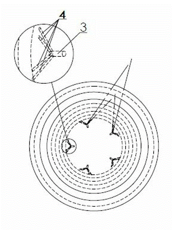
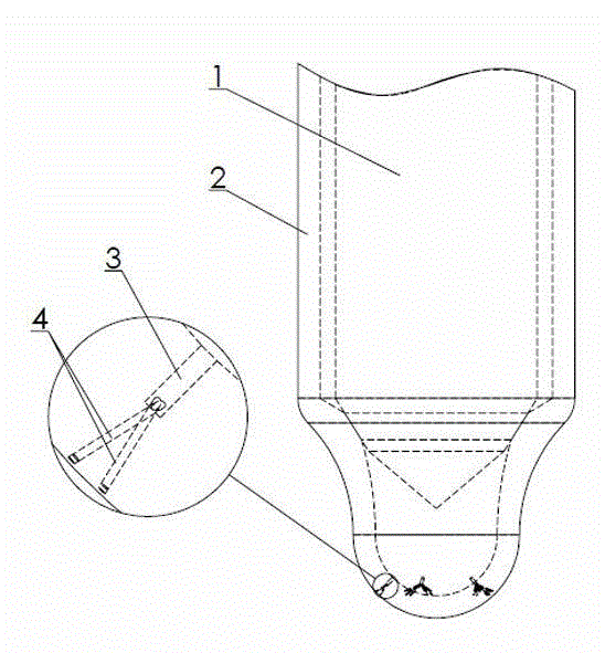
[0012] Examples of the present invention figure 1 , figure 2 As shown, the disturbing nozzle injector includes a needle valve 1 and a needle valve body 2, which is characterized in that there are at least five main injection holes 3 in a uniform array along its center line in the needle valve body 2, corresponding to each main injection hole 3 There are four sub-nozzles 4 on the needle valve body 2, the sub-nozzles 4 communicate with the main nozzle 3, and branch at the same position in the main nozzle 3, each sub-nozzle 4 on the main nozzle 3 The two groups are equally divided into a left half group and a right half group, and the left half group and the right half group are distributed around the center line of the main nozzle hole 3, and the sub nozzle holes 4 in the left half group and the right half group The bifurcated positions in the nozzle holes 3 are arranged in a divergent shape at the center, the cross-sectional area of ​​the main nozzle holes 3 is smaller than t...


PUM


Abstract

The invention discloses a fuel injector with perturbation spray nozzles, which is characterized in that at least three main spray orifices are arrayed in a needle valve body; more than four even numbered auxiliary spray orifices are arranged on each main spray orifice; the auxiliary spray orifices are communicated with the corresponding main spray orifice, branched at the same position in the corresponding main spray orifice, and divided into a left group and a right group that are distributed on the left and the right by taking the central line of the corresponding main spray orifice as the midline; the conical surfaces of conical fuel mist sprayed by two adjacent auxiliary spray orifices respectively in the left and the right groups of two adjacent main spray orifices are tangent; the conical surfaces of conical fuel mist sprayed by the auxiliary spray orifices, which are in one-to-one correspondence, respectively in the left and the right groups and arranged sideward the two adjacent auxiliary spray orifices, are sequentially and respectively tangent; and the cross section area of each main spray orifice is less than the sum of the cross section areas of the corresponding auxiliary spray orifices. Due to the change of movement direction, the fuel generates stronger vortexes in the branch position of the auxiliary spray orifices, and then is sprayed out from the auxiliary spray orifices; the conical fuel mist sprayed by the auxiliary spray orifices passes through in a two-two tangency manner; therefore, the stronger perturbation is formed due to different directions, and the atomization intensity of the fuel is enhanced.

Description

technical field [0001] The invention relates to an in-cylinder direct-injection internal-combustion engine fuel injection device, in particular to a disturbance nozzle fuel injector, which is used to realize fuel disturbance injection after swirl. Background technique [0002] With the advancement of science and technology, the birth of the internal combustion engine has led to the vigorous development of society. At present, the number of internal combustion engines is huge and is still increasing rapidly. While bringing convenience to mankind, it also aggravates environmental pollution and energy shortages. The emissions of internal combustion engines and the improvement of fuel utilization are particularly important. The degree of atomization of fuel oil in internal combustion engines has a great impact on the economy and emissions of the engine. The methods to increase the atomization intensity mainly include increasing the injection pressure and organizing the fuel vort...

Claims


Application Information

Patent Timeline
Patent Type & Authority Applications(China)
IPC IPC(8): F02M61/10F02M61/18
Inventor 傅琳靖海国
Owner 中国船舶重工集团公司第七〇三研究所
Why Eureka
Try Eureka