Liquid lubricating system specially used for high-speed bearing

A liquid-lubricated, high-speed bearing technology, applied in the field of space and aviation bearing lubrication, can solve the problems of complex structure, large impact force of bearings, and increased strength requirements of parts, and achieves simplified bearing lubrication system, simplified supply system, The effect of flexible bearing arrangements

Inactive Publication Date: 2014-07-30
BEIHANG UNIV
View PDF5 Cites 0 Cited by
  • Summary
  • Abstract
  • Description
  • Claims
  • Application Information

AI Technical Summary

Problems solved by technology

Jet lubrication is directly pressurized and sprayed by an oil pump through the nozzle, which requires the use of a high-pressure oil pump and nozzle, which not only produces a great impact on the bearing, but also increases the strength requirements of the components in the system and increases the cost
Oil mist lubrication is to atomize the lubricating oil and transport it to the lubrication point. The oil mist formed in the atomization device is not easy to produce the oil film required for lubrication at the lubrication point. It is necessary to install a condensation nozzle at the lubrication point so that the oil mist can be condensed. Drop-shaped oil particles are formed behind the mouth. In order to transport the oil mist, an air compression system must be equipped. These additional devices complicate the structure of the oil mist lubrication system, and the transmission distance of the oil mist is also limited.
Compared with oil-mist lubrication, oil-air lubrication replaces the condensation nozzle with an oil-air distributor, which increases the cost and makes the structure more complicated.

Method used


Image

  • Liquid lubricating system specially used for high-speed bearing
  • Liquid lubricating system specially used for high-speed bearing

Examples


Embodiment Construction

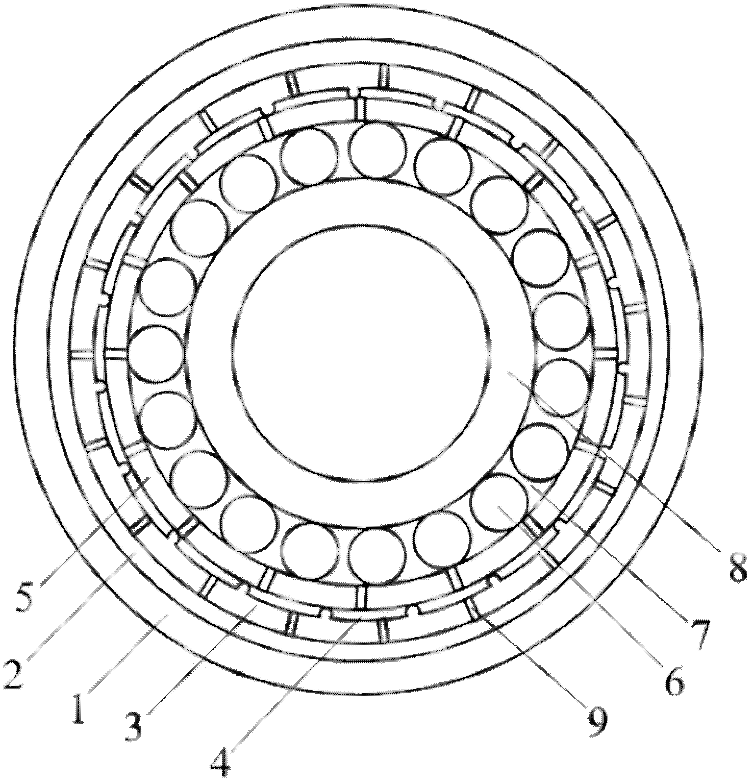
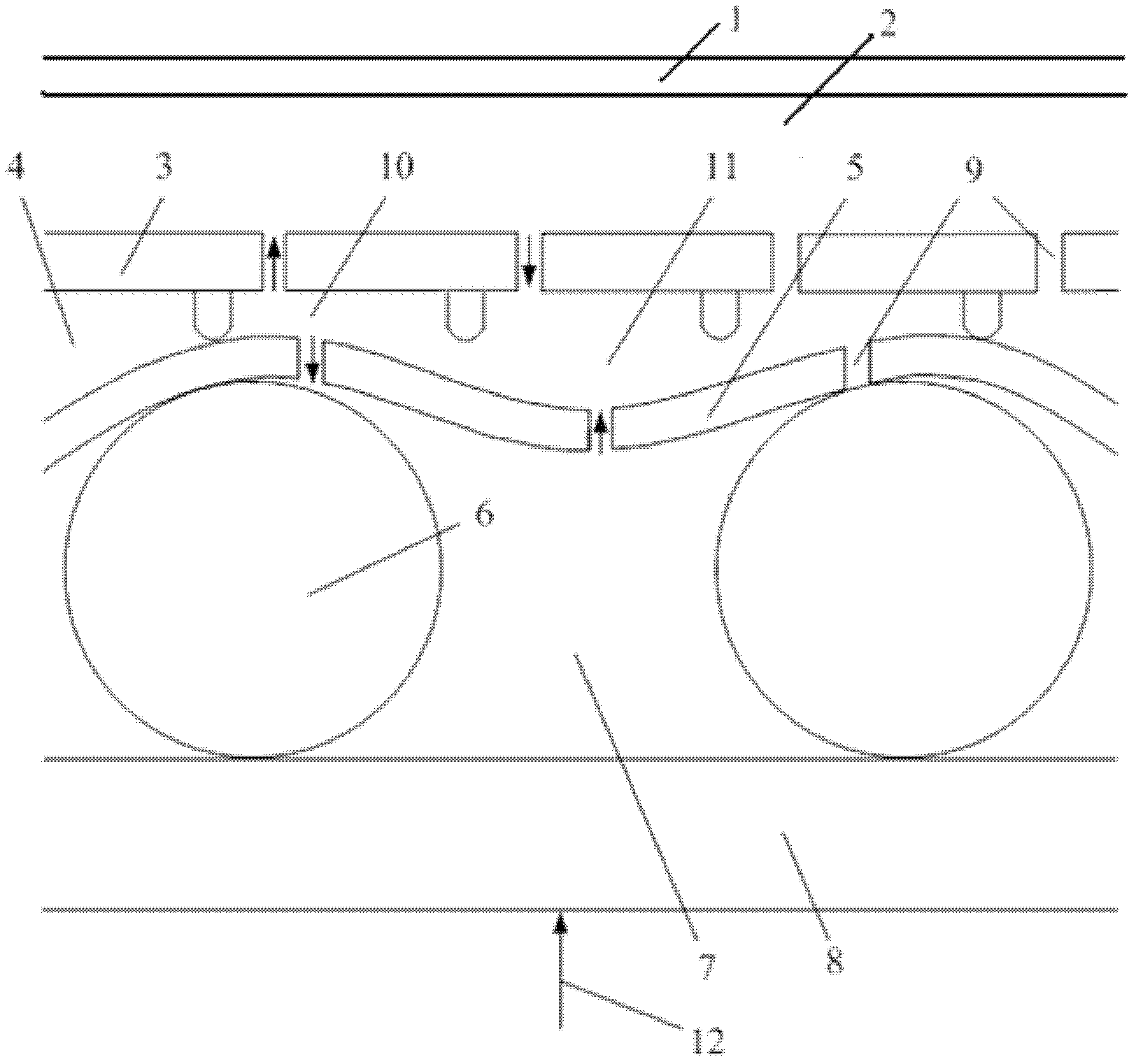
[0026] The present invention is a liquid lubrication system specially used for high-speed bearings, which includes a bearing inner ring 8, a rolling body 6, an elastic layer 5, a bearing outer ring 3, an external oil storage chamber 2, an internal oil storage chamber 4, a communication hole 9 and a bearing Seat 1, the positional connection relationship between them is: the bearing inner ring 8 is located at the inner end of the bearing, the rolling element 6 is arranged between the bearing inner ring 8 and the elastic layer 5, the elastic layer 5 is located outside the rolling element 6, and its inner circular surface In contact with the rolling element 6, the internal oil storage chamber 4 is set between the elastic layer 5 and the bearing outer ring 3, the external oil storage chamber 2 is located outside the bearing outer ring 3, and the communication holes 9 are distributed between the bearing outer ring 3 and the elastic layer 5 Above, the bearing seat 1 is located at the ...


PUM


Abstract

The invention discloses a liquid lubricating system specially used for a high-speed bearing. The liquid lubricating system comprises a bearing inner race, rolling elements, an elastic layer, a bearing outer race, an external oil-storage chamber, an internal oil-storage chamber, communication holes and a bearing pedestal. The bearing inner race is arranged at an inner end of a bearing. The rolling elements are arranged between the bearing inner race and the elastic layer. The elastic layer is arranged at outer parts of the rolling elements. The surface of an inner circle of the elastic layer contacts with the rolling elements. The internal oil-storage chamber is arranged between the elastic layer and the bearing outer race. The external oil-storage chamber is arranged at an outer part of the bearing outer race. The communication holes are arranged in the bearing outer race and the elastic layer. The bearing pedestal is arranged at the outermost layer of the bearing. The cambered surface of an inner circle of the bearing pedestal is an outer wall surface of the external oil-storage chamber. The power is produced by vibration of the elastic layer. Through the vibration of the elastic layer, a positive pressure zone and a negative pressure zone are produced in the internal oil-storage chamber and thus a force necessary for driving lubricating oil to flow is provided so that the uniformity and the reliability of lubricating oil distribution are ensured and a bearing lubricating oil supply system is simplified effectively. The liquid lubricating system specially used for a high-speed bearing has wide application prospects in the technical field of lubrication of a bearing used for aviation and aerospace.

Description

technical field [0001] The invention relates to a liquid lubricating system specially used for high-speed bearings, belonging to the technical field of lubricating space and aviation bearings. Background technique [0002] As the bearing speed in the aviation field is getting higher and higher, the choice of lubrication method is particularly critical. A good lubrication method must ensure the accuracy and operation stability of the entire system. The choice of lubrication method is related to the load, speed, allowable temperature rise and bearing type of the bearing. At present, the lubrication methods of high-speed bearings for aviation mainly include jet lubrication, oil mist lubrication and oil-air lubrication. Injection lubrication is directly pressurized and sprayed by an oil pump through the nozzle, which requires the use of a high-pressure oil pump and nozzle, which not only produces a large impact on the bearing, but also increases the strength requirements of the...

Claims


Application Information

Patent Timeline
Patent Type & Authority Patents(China)
IPC IPC(8): F16C33/66F16C27/04
Inventor 姬芬竹杜发荣郭雨琛徐斌杨世春
Owner BEIHANG UNIV
Why Eureka
Try Eureka