
Horizontal hot water boiler

A hot water boiler and horizontal technology, applied in the field of hot water boilers, can solve the problems of affecting the combustion state of fuel, not being strong enough, falling on the coal seam, etc., and achieve the effects of increasing the service life, alleviating the burden, and facilitating the removal of carbon deposits.

Inactive Publication Date: 2012-10-10
蒋恩良
View PDF6 Cites 3 Cited by
  • Summary
  • Abstract
  • Description
  • Claims
  • Application Information

AI Technical Summary

Problems solved by technology

The combustion chamber and the heat-absorbing structure belong to the upper and lower conjoined structure, which has the advantages of small footprint and compact structure, but there are also shortcomings: 1. Because the high-temperature flue gas generated when the fuel on the grate burns directly washes down the lower tube plate and enters the pyrotechnics Tube bundles, local high temperature and thermal expansion stress are unavoidable; the distance from the grate to the lower tube plate is relatively short, and when the amount of coal burned increases and the combustion intensity increases, insufficient combustion is almost inevitable; When carbon deposits, carbon deposits will fall on the coal seam and be ignited and then smoke will appear; if the combustion intensity of the 3 vertical vertical fire tube hot water boiler is not strong enough at the beginning of each operation, and if the water temperature is relatively high at this time Low, more condensed water will be generated in the heat-absorbing pipe, and the condensed water will easily fall on the fuel layer, which will affect the combustion state of the fuel in the combustion chamber

Method used


Image

  • Horizontal hot water boiler
  • Horizontal hot water boiler

Examples


Embodiment Construction

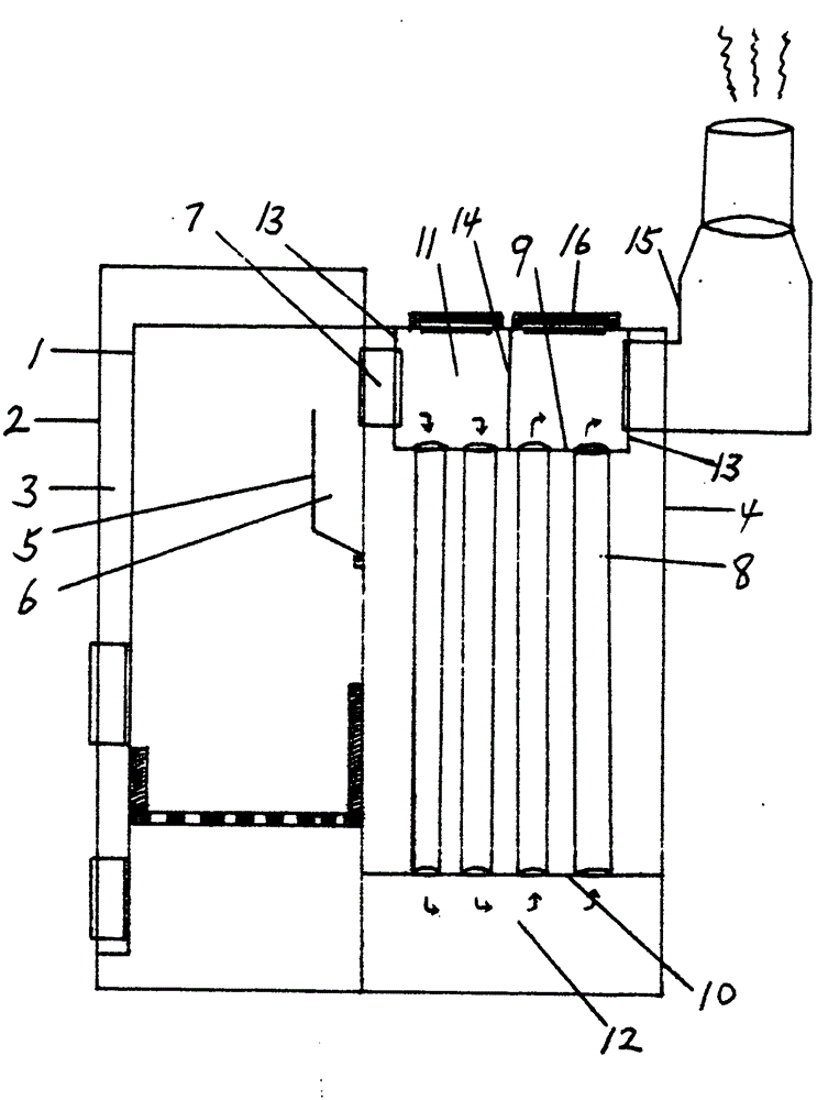
[0015] The invention is divided into two parts, a relatively independent combustion chamber and a radiator. Above the combustion chamber, there is a buffer plate 5 and a settling chamber 6 formed by the buffer plate. There is a high-temperature flue gas outlet 7 leading to the smoke chamber on the first stroke of the radiator near the radiator.

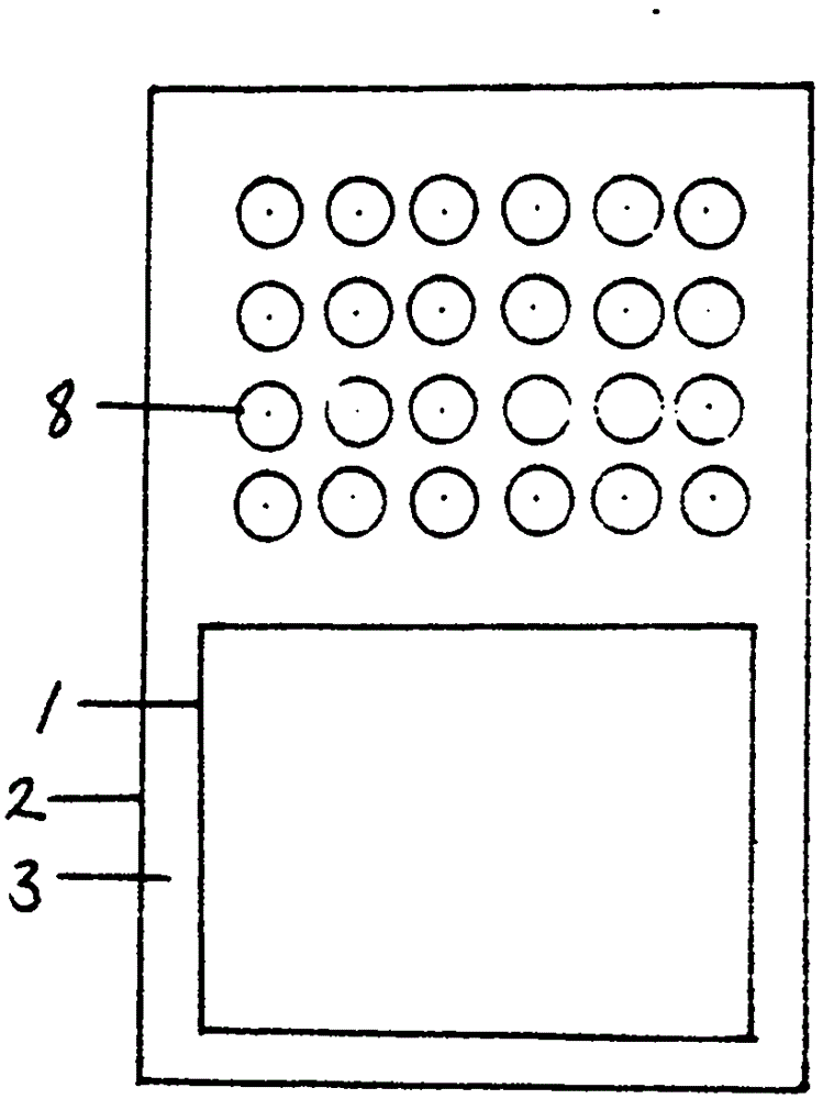
[0016] Between the combustion chamber liner 1 and the shell 2 is a membrane-type water-cooled wall 3, and the top of the combustion chamber is also a membrane-type water-cooled wall. The shell 4 of the heat absorber and the shell of the combustion chamber are essentially an integrated structure. The working medium in the shell of the device is also the same.

[0017] The pyrotechnic tube bundle composed of pyrotechnic tubes 8 is between the upper tube plate 9 and the lower tube plate 10, the upper tube plate is the upper smoke chamber 11, and the lower tube plate is the lower smoke chamber 12. The carbon deposits removed from the pyr...


PUM


Abstract

A horizontal hot water boiler belongs to the technical field of boilers. According to the boiler, the running time and the running distance of high-temperature smoke before entering a heat absorber of a smoke and fire tube are prolonged, so that fuels can be burned sufficiently; the phenomenon that accumulated carbon falls on a fuel bed and is smoky in a vertical fire tube boiler can be avoided when the accumulated carbon is removed; and during the initial running period of the horizontal hot water boiler, the phenomenon that condensate water falls on the fuel bed so as to affect the burning can not occur, an upper smoke chamber selects a water cooling structure, and a lower smoke chamber selects a non-water-cooling structure, so that the rear of a lower tube plate is obviously larger than that of an upper tube plate, a smoke tube positioned on the lower tube plate is far away from the edge of the tube plate, so that the stress caused by thermal expansion can be alleviated. A vertical baffle plate is additionally arranged on the upper smoke chamber of the heat absorber, so that two strokes of the high-temperature smoke in the heat absorber are realized. A hand hole door for removing accumulated carbon is arranged on the upper surface of the upper smoke chamber with two strokes of smoke tube bundles, the hand hole door for removing accumulated carbon can be opened to remove the accumulated carbon, and the accumulated carbon can be removed without opening the hand hole door for removing the accumulated carbon by adopting a pre-embedded smoke tube brush structure.

Description

Technical field [0001] The invention relates to a hot water boiler, in particular to a civil horizontal hot water boiler. Background technique [0002] The vertical vertical fire tube structure hot water boiler is composed of a combustion chamber, a lower tube plate, a pyrotechnic tube bundle, an upper tube plate, and an upper smoke chamber. The combustion chamber and the heat-absorbing structure belong to the upper and lower conjoined structure, which has the advantages of small footprint and compact structure, but there are also shortcomings: 1. Because the high-temperature flue gas generated when the fuel on the grate burns directly washes down the lower tube plate and enters the pyrotechnics Tube bundles, local high temperature and thermal expansion stress are unavoidable; the distance from the grate to the lower tube plate is relatively short, and when the amount of coal burned increases and the combustion intensity increases, insufficient combustion is almost inevitabl...

Claims


Application Information

Patent Timeline
Patent Type & Authority Applications(China)
IPC IPC(8): F24H1/44F24H9/18F24H9/00
Inventor 蒋恩良
Owner 蒋恩良
Learn More