Liquid separating device capable of separating liquid from metal chip materials

A metal cutting and deliquoring technology, applied in non-progressive dryers, dryers, lighting and heating equipment, etc., can solve problems such as damage to the health of operators, consumption of heat energy, and environmental pollution

Active Publication Date: 2014-04-30
KEHUA HLDG
View PDF5 Cites 0 Cited by
  • Summary
  • Abstract
  • Description
  • Claims
  • Application Information

AI Technical Summary

Problems solved by technology

It also produces and emits a large amount of steam and smoke during baking, which also consumes heat energy, damages the health of operators and pollutes the environment

Method used


Image

  • Liquid separating device capable of separating liquid from metal chip materials
  • Liquid separating device capable of separating liquid from metal chip materials
  • Liquid separating device capable of separating liquid from metal chip materials

Examples


Embodiment Construction

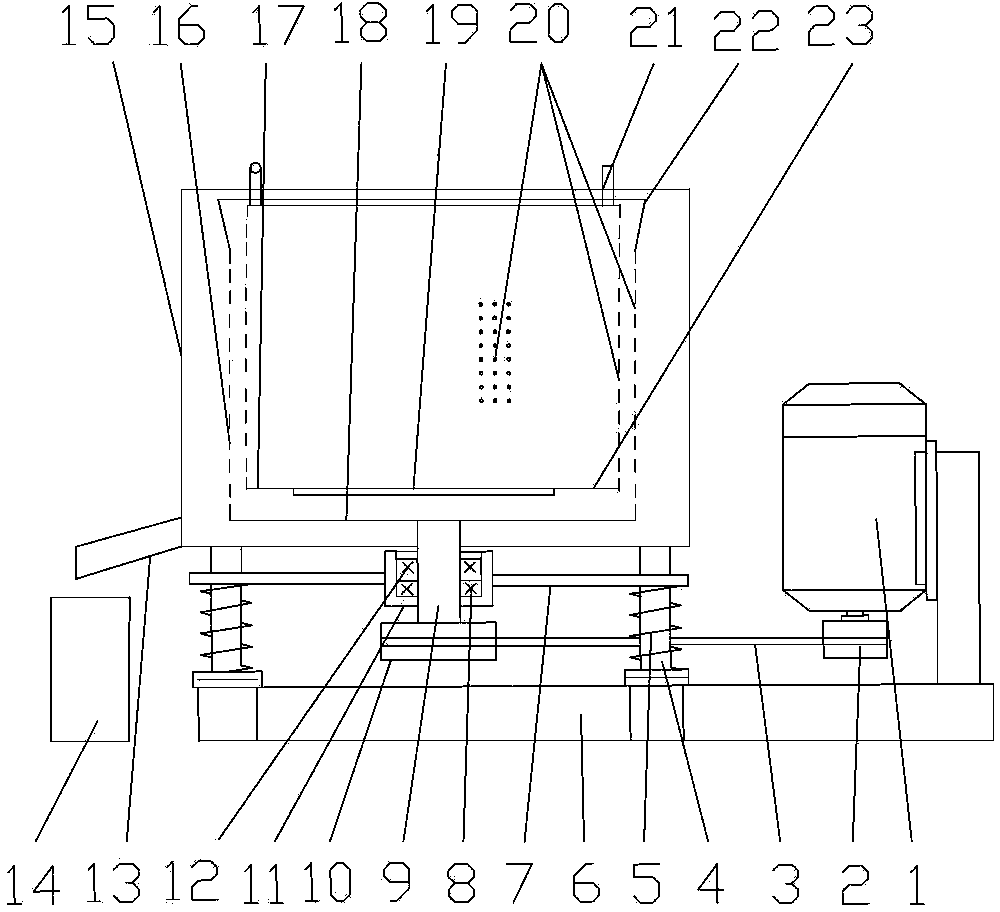
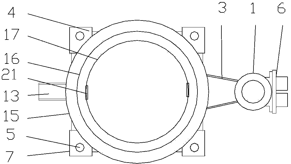
[0013] The embodiment shown in each figure is as follows: a dehydration device capable of dehydrating metal swarf. Four positioning guide posts 4 and the motor 1 are installed on the base 6 . Springs 5 ​​are all sleeved on the four positioning guide posts 4 . Four positioning guide pillars 4 upper ends are equipped with frame 7 and circular outer bucket 15 successively. Frame 7 is contained in spring 5 tops. The liquid outflow pipe 13 is equipped with in the lower part of the circular outer barrel 15 side walls. The bearing block 11 that bearing A8 and bearing B12 are housed in the middle is contained in the middle part of frame 7, and main shaft 9 is contained in the middle of bearing A8 and bearing B12. Main shaft V-belt pulley 10 is equipped with in main shaft 9 bottoms, and motor shaft V-belt pulley 2 is housed on the motor shaft of motor 1 bottom, is connected by V-belt 3 between main shaft V-belt pulley 10 and motor shaft V-belt pulley 2. A perforated cylinder 16 wit...


PUM


Abstract

The invention relates to a liquid separating device capable of separating liquid from metal chip materials. Four positioning guide columns and a motor are installed on a base. A spring respectively sleeves each positioning guide column. The upper end of each positioning guide column is sequentially provided with a stander and a circular outer barrel. A bearing seat with a bearing A and a bearing B in the middle part is installed in the middle part of the stander, and a main shaft is installed between the bearing A and the bearing B. The lower part of the main shaft is connected with the motor through a triangular adhesive tape. A porous circular barrel is fixedly installed on the main shaft. A porous movable suspension barrel is movably installed in the middle of the porous circular barrel, and the bottom of the porous movable suspension barrel is provided with a movable soleplate. A suspension ring is installed on the porous movable suspension barrel. Both the porous circular barrel and the porous movable suspension barrel are provided with a plurality of liquid holes. A liquid holding barrel is arranged below a liquid flow-out pipe of the circular outer barrel. When the liquid separating device is used for separating the liquid from the metal chip materials, less vapor and less smoke, which are mixed with hydrocarbon, are produced, the heat energy is not wasted, the environment is not polluted, and the body health of the operation personnel is not damaged. The liquid separating device can be used for recycling the mixed liquid of cutting liquid and lubricating oil and for further processing and utilizing the metal chip materials.

Description

technical field [0001] The invention relates to a dehydration device, in particular to a dehydration device capable of dehydrating metal cuttings. It belongs to the equipment for furnace charge treatment in machinery manufacturing foundry workshop. Background technique [0002] In mechanical processing, various metal processing parts, especially the installation and matching parts of castings, must be cut, and a large amount of metal chips will be generated during the cutting process. These metal shavings can be recycled and reused. At present, the recycling rate of non-ferrous metal cuttings is relatively high. The scrap recycling rate of ferrous metals, especially alloy materials, is also increasing. Since a large amount of cutting fluid is used when cutting metal castings, it is also inevitable to mix with lubricating oil. Metal chips containing cutting fluid and lubricating oil will produce a large amount of vapor and smoke mixed with hydrocarbons when they encounter...

Claims


Application Information

Patent Timeline
Patent Type & Authority Patents(China)
IPC IPC(8): F26B11/02
Inventor 张笑山
Owner KEHUA HLDG
Why Eureka
Try Eureka