Device for sampling biomembrane on outer surface of pipe growth ring

A sampling device and biofilm technology, applied in the direction of sampling devices, etc., can solve the problems of changing the growth environment and organizational structure of biofilm microorganisms on the outer surface of the pipeline growth ring, inability to sample online, and inconvenient sampling, etc., to achieve convenient and fast installation and antifreeze Reliability, easy sampling effect

Active Publication Date: 2012-10-10
HARBIN INST OF TECH
View PDF4 Cites 8 Cited by
  • Summary
  • Abstract
  • Description
  • Claims
  • Application Information

AI Technical Summary

Problems solved by technology

[0004] The purpose of the present invention is to solve the problem of using the prior art to sample the biofilm on the outer surface of the pipeline growth ring, which is inconvenient for sampling, cannot be sampled online and cha

Method used


Image

  • Device for sampling biomembrane on outer surface of pipe growth ring
  • Device for sampling biomembrane on outer surface of pipe growth ring

Examples


Example Embodiment

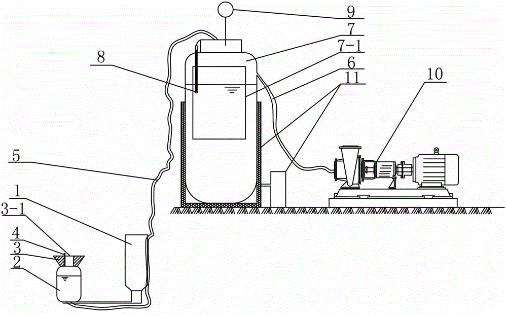
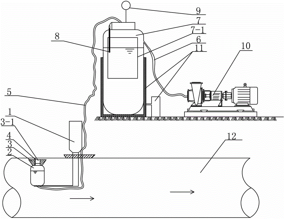
[0008] Specific implementation mode one: combine figure 1 and figure 2 To illustrate this embodiment, a biofilm sampling device on the outer surface of a pipe growth ring in this embodiment includes an electric push rod 1, a sampling bottle 2, a frustum-shaped rubber stopper 3, a circular scraper 4, a rubber tube 5, a connecting tube 6, a collection Tank 7, thermometer 8, pressure gauge 9, vacuum pump 10, and electric heating element 11; the push rod end of the electric push rod 1 is connected to the bottom of the sampling bottle 2, and the electric push rod 10 is used for sealing connection with the pipeline 12, in the shape of a truncated cone The small-diameter end of the rubber plug 3 is inserted into the mouth of the sampling bottle 2, and the middle of the small-diameter end and the middle of the large-diameter end of the frustum-shaped rubber plug 3 are provided with a coaxial through hole 3-1, which is located in the frustum-shaped rubber plug 3 A circular scraper 4 ...

Example Embodiment

[0014] Specific implementation mode two: combination figure 1 This embodiment will be described. The connecting pipe 6 in this embodiment is a rubber connecting pipe. Such setting meets the design requirements and actual needs. Others are the same as in the first embodiment.

Example Embodiment

[0015] Specific implementation mode three: combination figure 1 Describe this embodiment, the collection tank 7 in this embodiment is a stainless steel collection tank. Such setting meets the design requirements and actual needs. Others are the same as in the first or second embodiment.

[0016] work process

[0017] combine figure 1 and figure 2 To illustrate the working process of the present invention, it is necessary to carry out ultraviolet (wavelength 265mm-266mm) sterilizing treatment on the inside of the sampling bottle and the airtight tank before work. Push the push rods together from the hole into the sampling point under investigation, and ensure that the moving direction of the electric push rod is consistent with the direction of the water flow, so as to prevent the biofilm on the outer surface of the growth ring that has been scraped off from being washed away by the reverse water flow, and ensure the sampling volume. Ensure that the hole between the elect...


PUM


Abstract

The invention relates to a device for sampling a biomembrane on the outer surface of a pipe growth ring and aims to solve the problems that the biomembrane on the outer surface of a pipe growth ring is inconvenient to sample and can not realize on-line sampling, and the microbial growth environment and tissue structure of the biomembrane on the outer surface of the pipe growth ring can be changed. The device comprises an electric push rod, a sampling bottle, a circular-truncated-cone-shaped rubber plug, a round scrapper, a rubber pipe, a connecting pipe, a colleting pot, a thermometer, a pressure gage, a vacuum pump and an electric heating element, wherein the rod-pushing end of the electric push rod is connected with the bottom of the sampling bottle; the round scrapper is connected at a through hole at the large diameter end of the circular-truncated-cone-shaped rubber plug; the bottom of the sampling bottle is connected with one end of the rubber pipe; the other end of the rubber pipe is connected with the inlet of the collecting pot; and the electric heating element is arranged at the periphery of the collecting pot. The device is used for sampling the biomembrane on the outer surface of the pipe growth ring.

Description

technical field [0001] The invention relates to a device for sampling biofilms on the outer surface of pipeline growth rings, in particular to a device for sampling biofilms on the outer surface of pipeline growth rings without stopping water by using a scraper. Background technique [0002] The inner wall of the water supply pipeline will form a growth ring during long-term operation. The growth ring refers to a complex composed of a yellowish brown, porous, and uneven layer of sediment, rust and sticky scale on the inner wall of the pipe; the growth ring is composed of From the inside to the outside are corrosion layer, post-sedimentation layer and biofilm layer. The existence of biofilm on the water supply pipeline will cause problems such as water quality, including the growth of pathogenic bacteria, the increase of chroma and turbidity, the intensification of pipeline corrosion, the shrinkage of water cross section, the occurrence of pipe burst, the increase of energy c...

Claims


Application Information

Patent Timeline
IPC IPC(8): G01N1/04
Inventor 高金良庄永伟刁美玲
Owner HARBIN INST OF TECH
Why Eureka
Try Eureka