Multi-beam array light-induced reflectivity imaging device and method

A reflectivity, light-induced technology, applied in the direction of material excitation analysis, can solve the problem of long time, and achieve the effect of improving stability, reducing cost, and improving imaging speed.

Active Publication Date: 2012-10-10
合肥利弗莫尔仪器科技有限公司
View PDF6 Cites 9 Cited by
  • Summary
  • Abstract
  • Description
  • Claims
  • Application Information

AI Technical Summary

Problems solved by technology

[0011] The technical problem to be solved by the present invention is to provide a multi-beam array light-induced reflectivity imaging device and method to solve the problem that the time-consuming point-by-point scanning imaging method in the light-induced reflectivity application is too long

Method used


Image

  • Multi-beam array light-induced reflectivity imaging device and method

Examples


Embodiment Construction

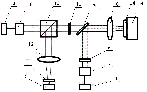
[0025] See figure 1 , a multi-beam array light-induced reflectivity imaging device, including a pump light source 1, a detection light source 2, a photodetector 3 and a sample stage 4; between the pump light source 1 and the sample stage 4, a pump light diffraction spectroscopic device is arranged in sequence 5. An array modulator 6, a dichroic mirror 7, and a focusing imaging lens 8; between the detection light source 2 and the sample stage 4, a detection light diffraction spectroscopic device 9, a polarizing beam splitter 10, and a quarter-wave plate 11 are sequentially arranged , dichroic mirror 7 and focusing imaging lens 8; photodetector 3 is arranged on the rear end of polarizing beam splitter 10, and between polarizing beam splitting mirror 10 and photodetector 3 is provided with detection light focusing lens 12 and detection light filter The device 13; both the pumping light source 1 and the detection light source 2 can be laser light sources or monochromatic light sou...


PUM


Abstract

The invention discloses a multi-beam array light-induced reflectivity imaging device and a method thereof. The multi-beam array light-induced reflectivity imaging device comprises a pump light source, a detecting light source, a diffraction light splitting device, an array optical modulator, a dichroic mirror, an optical lens, a polarization light splitter, an optical filter and an optical detector. According to the invention, light reflectance changes of the detecting light are induced by the pump light and reflectance imaging is carried out. The imaging speed improves greatly compared with the traditional method of scanning a sample point by point. The point-by-point scanning is further not needed. Specific detection and imaging instrument design can therefore avoid the use of a moving part. With the device and the method of the invention, the stability of an instrument is improved, the production cost is reduced, further miniaturization is promoted and application areas are broadened.

Description

[0001] technical field [0002] The invention relates to the field of multi-beam array light-induced reflectance imaging, in particular to a two-dimensional light-induced reflectance imaging device and method using a diffraction spectroscopic device to split light. Background technique [0003] Light-induced reflectance imaging is a relatively sensitive non-contact optical measurement method. The basic principle is based on the fact that the reflectivity of the material will change under the action of light (hereinafter referred to as pump light). In most cases, this change in reflectivity is caused by the local temperature rise caused by the absorption of pump light energy by the material. The physical process can be simplified and expressed as: [0004] (1) [0005] in, is the change in reflectivity of the material surface, is the material reflectivity temperature coefficient, is the temperature change caused by the absorption of pump light energy by t...

Claims


Application Information

Patent Timeline
Patent Type & Authority Applications(China)
IPC IPC(8): G01N21/63
Inventor 吴周令陈坚
Owner 合肥利弗莫尔仪器科技有限公司
Why Eureka
Try Eureka