
Non-isolated bi-directional DC-DC converter control method

A technology of DC-DC and converter control, which is applied in the direction of control/regulation system, conversion equipment without intermediate conversion to AC, conversion of DC power input to DC power output, etc., and can solve the fluctuation of controlled voltage and controlled current, etc. problem, to achieve the effect of improving response speed and control accuracy

Active Publication Date: 2012-10-10
SHANGHAI MITSUBISHI ELEVATOR CO LTD
View PDF8 Cites 20 Cited by
  • Summary
  • Abstract
  • Description
  • Claims
  • Application Information

AI Technical Summary

Problems solved by technology

[0008] For the above voltage and current double closed-loop control method, since the voltage and current loops both adopt the feedback control method, the control output will be adjusted only when the voltage error and current error occur, so when the non-isolated bidirectional DC-DC When the load power or current of the converter changes suddenly, the controlled voltage and controlled current will fluctuate greatly. Obviously, the ordinary voltage and current double closed-loop control method is not suitable for occasions with severe load changes and high control precision requirements.

Method used


Image

  • Non-isolated bi-directional DC-DC converter control method
  • Non-isolated bi-directional DC-DC converter control method
  • Non-isolated bi-directional DC-DC converter control method

Examples


Embodiment 1

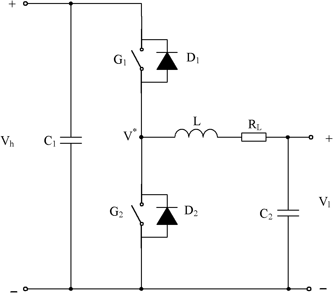
[0026] Such as figure 2 As shown, in this embodiment, the high voltage side of the non-isolated bidirectional DC-DC converter is connected to a DC load, or further includes a DC power supply, and the low voltage side is connected to an energy storage device. Here, the DC load can be energy-consuming DC load or regenerative DC load, such as the combination of DC / AC (direct current / alternating current) inverter and motor; DC power generally refers to any functionally equivalent The device of DC power supply can be a real DC power supply or other substitutes with the properties of DC power supply, such as the combination of three-phase commercial power supply and AC / DC (alternating current / direct current) rectifier; the energy storage device is a battery, a super capacitor and other devices capable of charging and discharging. For the convenience of analysis, in the follow-up analysis, the energy storage device is uniformly modeled as a capacitor C ES , and denote its terminal...

Embodiment 2

[0036] The control target of this embodiment is to reduce the voltage V on the low-voltage side of the non-isolated bidirectional DC-DC converter l remains at its commanded value V lref situation.

[0037] Since the control target of Embodiment 1 is to reduce the voltage V on the high voltage side of the non-isolated bidirectional DC-DC converter h remains at its commanded value V href Therefore, its working principle is very similar to this embodiment, and those skilled in the art can obtain the control method of embodiment 1 by making slight changes according to the description in embodiment 1, so the situation of embodiment 2 will not be repeated here.

[0038] In the present invention, the desired voltage and the high voltage side terminal voltage V of the non-isolated bidirectional DC-DC converter h The quotient of is the desired duty cycle corresponding to the desired voltage, where the high voltage side terminal voltage V h It is an actual value or a preset value; t...


PUM


Abstract

The invention discloses a non-isolated bi-directional DC-DC converter control method. A double closed-loop control structure formed by an outer voltage loop and an inner current loop is employed to control single end voltage, the inner current loop employs a current feedback control mode or a current composite control mode, and the sum of current feedback control output and current feedforward control output is control output of the inner current loop. According to the method, the unified control of the non-isolated bi-directional DC-DC converter in a buck mode and a boost mode can be realized, through employing the composite control mode, a response speed of the voltage loop and / or the current loop can be effectively raised, and the performance of the non-isolated bi-directional DC-DC converter is improved.

Description

technical field [0001] The invention relates to the field of power electronic converters, in particular to a control method for a non-isolated bidirectional DC-DC converter. Background technique [0002] A bidirectional DC-DC (direct current-direct current) converter essentially refers to a type of DC-DC converter capable of bidirectional transmission of energy, which is functionally equivalent to two unidirectional DC-DC converters with different input and output voltage polarities. Change, input and output current direction can be changed. Bidirectional DC-DC converters are mainly used in applications that require bidirectional energy flow, such as battery chargers, uninterruptible power supplies (UPS), electric vehicles, photovoltaic power generation, wind power generation, fuel cells, and elevator energy saving based on energy storage devices. The application of bidirectional DC-DC converters in these occasions can effectively reduce the volume, weight and cost of the s...

Claims


Application Information

Patent Timeline
IPC IPC(8): H02M3/10H02M3/155
Inventor 陈玉东何晓光
Owner SHANGHAI MITSUBISHI ELEVATOR CO LTD
Learn More