Rotary piezoelectric generation device

A power generation device and rotary press technology, applied in the field of micro energy, can solve the problems of reducing the service life, reducing the efficiency conversion of the rotating shaft, mechanical energy loss, etc., and achieve the effect of avoiding energy loss, avoiding the structure system, and avoiding the reduction of life span

Active Publication Date: 2012-10-10
NANJING UNIV OF AERONAUTICS & ASTRONAUTICS
View PDF5 Cites 38 Cited by
  • Summary
  • Abstract
  • Description
  • Claims
  • Application Information

AI Technical Summary

Problems solved by technology

However, this solution has the following disadvantages: 1. Use contact mode to transfer energy, resulting in loss of mechanical energy and reduced service life
However, the extension direction of the copper beams of the bimorph array of the device is set along the axial direction of the rotating shaft, causing the impact force of the permanent magnet on the bimorphs to be perpendicular to its vibration direction,

Method used


Image

  • Rotary piezoelectric generation device
  • Rotary piezoelectric generation device
  • Rotary piezoelectric generation device

Examples


Embodiment Construction

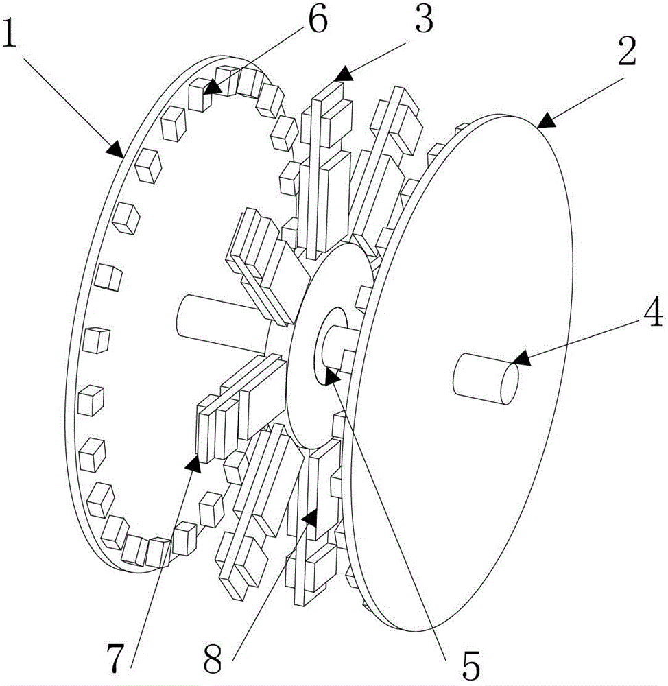
[0020] The accompanying drawings disclose, without limitation, the structural schematic diagrams of the preferred embodiments involved in the present invention; the technical solution of the present invention will be described in detail below in conjunction with the accompanying drawings.

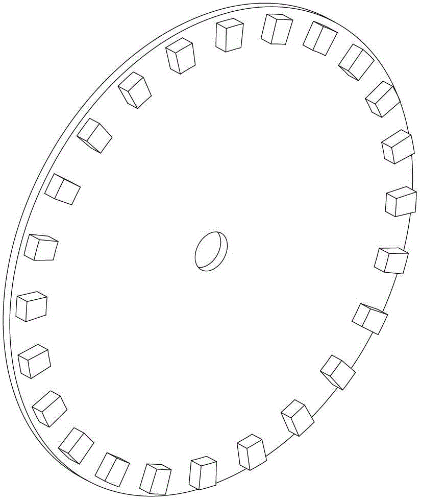
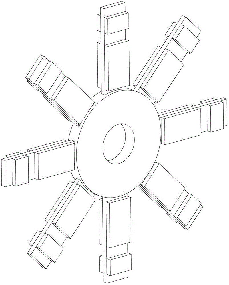
[0021] Such as figure 1 As shown, the rotary piezoelectric power generation device of the present invention includes a rotating shaft and a front excitation wheel, a piezoelectric twin crystal beam array, and a rear excitation wheel respectively installed on the rotation shaft. The front excitation wheel 1 and the rear excitation wheel 2 will be The piezoelectric double crystal beam array 3 is sandwiched in the middle to form a sandwich structure, and there is a certain gap between the three; the front excitation wheel 1 and the rear excitation wheel 2 are both rigidly connected to the rotating shaft 4, and the piezoelectric double crystal beam array 3 passes through the bearing 5 Connected...


PUM


Abstract

The invention discloses a rotary piezoelectric generation device, which comprises a rotary shaft, a front excitation wheel, a rear excitation wheel and a piezoelectric twin-crystal beam array, wherein the piezoelectric twin-crystal beam array is arranged between the front excitation wheel and the rear excitation wheel; the front excitation wheel and the rear excitation wheel respectively comprise a wheel disk and excitation permanent magnet blocks; the excitation permanent magnet blocks of the front excitation wheel and the rear excitation wheel are staggered spatially; the piezoelectric twin-crystal beam array comprises hubs and piezoelectric twin-crystal beams; each piezoelectric twin-crystal beam comprises a cantilever beam; a piezoelectric ceramic wafer and a piezoelectric beam permanent magnet block are respectively arranged on a beam body of each cantilever beam; and permanent magnet repulsive force can be respectively formed between the piezoelectric beam permanent magnet blocks and the excitation permanent magnet blocks of the front excitation wheel and the rear excitation wheel. Therefore, by rotation of the rotary shaft, the two excitation wheels alternately apply repulsive force to the piezoelectric twin-crystal beams of the piezoelectric twin-crystal beam array, high frequency is generated, and high forced deformation is caused, so the rotation energy of the rotary shaft is effectively utilized.

Description

technical field [0001] The invention is a rotary piezoelectric power generation device, which belongs to the field of micro-energy technology, and is particularly suitable for collecting rotational mechanical energy changing in the environment. Background technique [0002] Using various vibration energies such as wind energy and water energy in nature to generate power and supply power to various micro-systems is in line with today's energy-saving, environmental protection, and low-carbon development trends. Among various energy harvesting methods, the use of piezoelectric materials for energy harvesting is more suitable for the low-frequency and random variation characteristics of environmental vibration energy. [0003] The power generation performance of the piezoelectric cantilever is proportional to the strain and vibration frequency of the piezoelectric ceramic. Priya of the United States invented a novel windmill type wind energy absorbing device (US2010 / 0052324A1)....

Claims


Application Information

Patent Timeline
IPC IPC(8): H02N2/18
Inventor 李华峰胡俊辉
Owner NANJING UNIV OF AERONAUTICS & ASTRONAUTICS
Why Eureka
Try Eureka