
Energy supply method and system

A technology for supplying system and energy, applied in the energy field, can solve the problem of low energy conversion efficiency of energy supply system, and achieve the effect of improving energy conversion efficiency

Active Publication Date: 2019-12-06
DONGFANG ELECTRIC (CHENGDU) HYDROGEN FUEL CELL TECH CO LTD
View PDF3 Cites 0 Cited by
  • Summary
  • Abstract
  • Description
  • Claims
  • Application Information

AI Technical Summary

Problems solved by technology

[0008] The main purpose of the present invention is to provide an energy supply method and system to solve the problem of low energy conversion efficiency of the energy supply system in the related art

Method used


Image

  • Energy supply method and system
  • Energy supply method and system
  • Energy supply method and system

Examples


Embodiment Construction

[0030] It should be noted that, in the case of no conflict, the embodiments in the present application and the features in the embodiments can be combined with each other. The present invention will be described in detail below with reference to the accompanying drawings and examples.

[0031] In order to enable those skilled in the art to better understand the solution of the present application, the technical solution in the embodiment of the application will be clearly and completely described below in conjunction with the accompanying drawings in the embodiment of the application. Obviously, the described embodiment is only It is an embodiment of a part of the application, but not all of the embodiments. Based on the embodiments in this application, all other embodiments obtained by persons of ordinary skill in the art without creative efforts shall fall within the scope of protection of this application.

[0032] It should be noted that the terms "first" and "second" in ...


PUM


Abstract

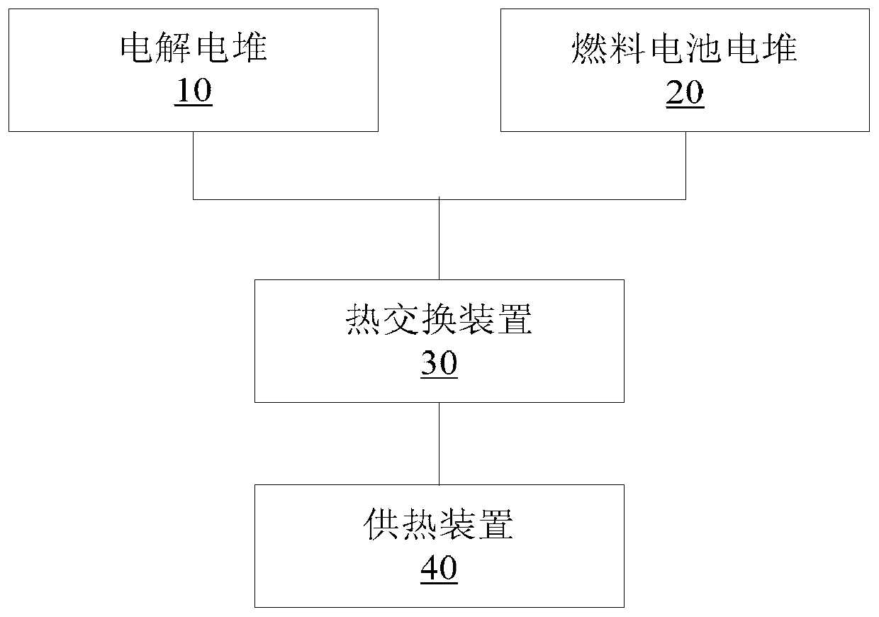
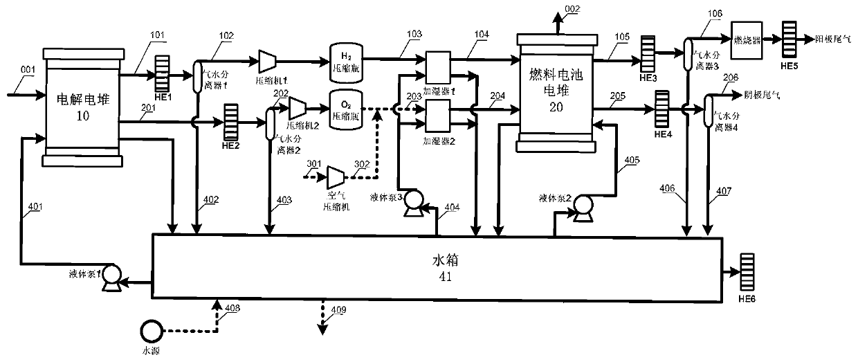
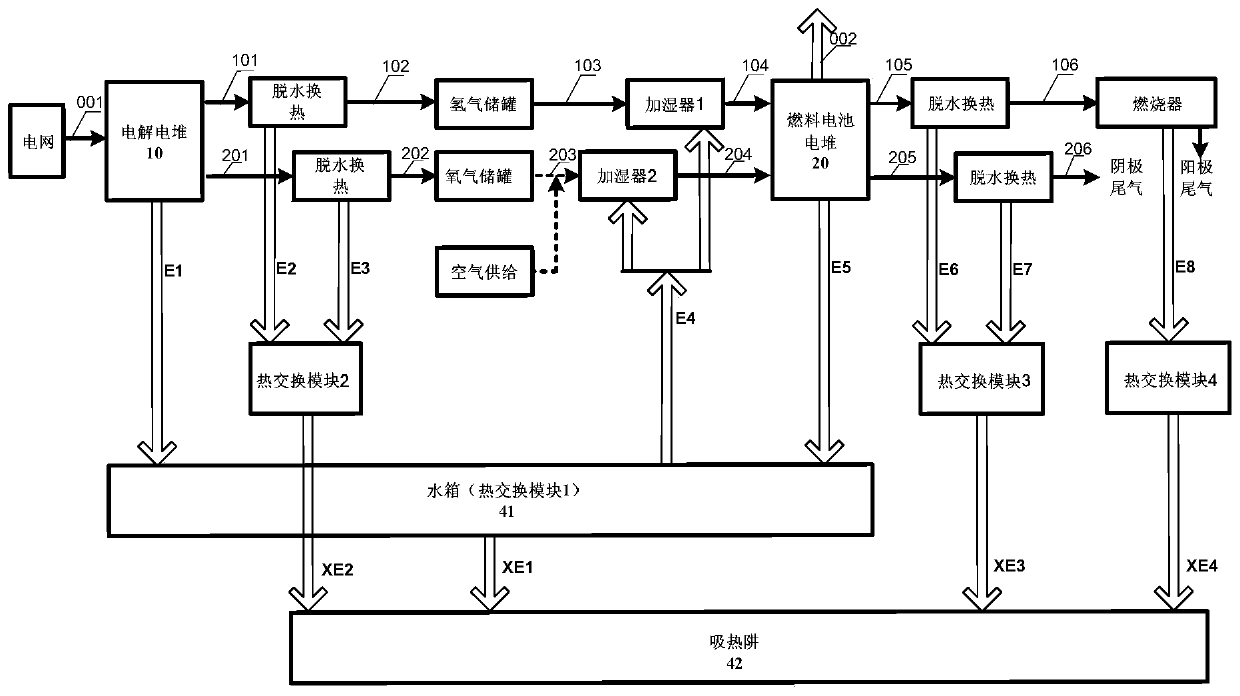
The invention discloses an energy supply method an energy supply system. The system comprises an electrolysis galvanic pile used for utilizing the electric energy to electrolyze water to produce an electrolysis gas, a fuel cell galvanic pile communicated with the electrolysis galvanic pile and used for outputting the electric energy according to a chemical reaction produced by the electrolysis gas, a heat exchanging device communicated with the electrolysis galvanic pile and / or fuel cell galvanic pile, and a heat supply device communicated with the heat exchanging device and used for outputting the heat energy through heat provided by the heat exchanging device, wherein when used for being communicated with the electrolysis galvanic pile, the heat exchanging device absorbs the heat produced in electrolysis of the electrolysis galvanic pile, and / or when used for being communicated with the fuel cell galvanic pile, the heat exchanging device absorbs the heat produced in the chemical reaction of the fuel cell galvanic pile. Through the method and the system, the problem of relatively low energy conversion efficiency of the energy supply system in the related technique is solved.

Description

technical field [0001] The present invention relates to the field of energy, in particular to an energy supply method and system. Background technique [0002] The combined heat and power system (referred to as the combined heat and power system) can provide heat and electricity to the community. The combined heat and power system can use a variety of energy sources, including the use of new energy, for example, through the combination of fuel cell stacks and electrolytic hydrogen production. The integrated heat and power cogeneration system can use new energy sources such as wind energy and solar energy to perform grid-connected peak regulation on the grid. The combined heat and power system using proton exchange membrane fuel cell stacks requires hydrogen to provide energy. Hydrogen is usually stored in the form of high-pressure hydrogen. The scale of the hydrogen storage device restricts the sustainability of the discharge, and hydrogen fuel needs to be regularly replenis...

Claims


Application Information

Patent Timeline
Patent Type & Authority Patents(China)
IPC IPC(8): H01M8/0656H01M8/04007
CPCH01M8/04007H01M8/0656Y02E60/50
Inventor 汤浩殷聪宋亚婷刘煜吴迪方明
Owner DONGFANG ELECTRIC (CHENGDU) HYDROGEN FUEL CELL TECH CO LTD
Learn More