Pressing-type rotary cleaning machine for cylindrical roller bearings

A cylindrical roller bearing, pressure-dynamic technology, applied in cleaning methods and appliances, cleaning methods using liquids, chemical instruments and methods, etc., can solve problems such as difficult cleaning, dirty cleaning, unsatisfactory bearing effect, etc. , to achieve the effect of improving cleaning effect and product quality

Active Publication Date: 2012-10-17
DALIAN GRANDWAY BEARING
View PDF10 Cites 14 Cited by
  • Summary
  • Abstract
  • Description
  • Claims
  • Application Information

AI Technical Summary

Problems solved by technology

[0002] Bearing cleaning generally adopts a through-type cleaning machine. This kind of cleaning machine can clean the bearing surface and individual parts, but the effect of cleaning the whole set of bearings with complex structure is not ideal, and the debris between the grooves, rolling elements and cages cannot be cleaned. Clean, especially the copper scrap impurities in the cage with strong adhesion are hidden in the inner cavity of the bearing, which is difficult to clean. There must be a cleaning machine that moves the bearing inner ring, rolling elements, and cage at the same time to achieve the cleaning effect

Method used


Image

  • Pressing-type rotary cleaning machine for cylindrical roller bearings
  • Pressing-type rotary cleaning machine for cylindrical roller bearings
  • Pressing-type rotary cleaning machine for cylindrical roller bearings

Examples


Embodiment Construction

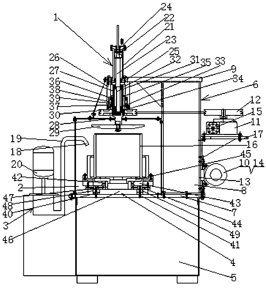
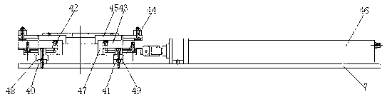
[0024] A press-type cylindrical roller bearing rotary cleaning machine, including a rotary oil cylinder assembly 1, a cleaning room 2, an oil spray mechanism 3, a workbench moving cylinder assembly 4, an oil tank 5, a box-type support 6, and a workbench 7 and power rotation mechanism;

[0025] The box support 6 includes a support box 8 and a support platform 9, the support platform 9 is fixed on the upper end cover of the support box 8, and the lower end of the support box 8 of the box support is fixed on the workbench 7;

[0026] The power transmission mechanism includes a motor 10, a worm gear reducer 11 and a first pulley 12, the motor 10 is fixed on the right side wall 13 of the support box 8, the output shaft of the motor 10 is equipped with a third pulley 14, the worm gear reducer 11 A fourth pulley 15 is installed on the input shaft of the worm gear reducer 11, a first pulley 12 is installed on the output shaft of the worm gear reducer 11, and the third pulley 14 is con...


PUM


Abstract

A pressing-type rotary cleaning machine for cylindrical roller bearings comprises a rotary feeding oil cylinder, an oil tank cleaning chamber, a motor, a speed reducer, a supporter, a spline shaft, a workbench, a rotatable workbench and a movable platform. The workbench is fixed on an upper end cover of the oil tank and the cleaning chamber is arranged on the workbench. A pressing plate push rod is connected on a lower end of a piston rod of the rotary feeding oil cylinder. The spline shaft is equipped on the pressing plate push rod and a spline shaft sleeve is equipped on the spline shaft. The spline shaft sleeve is connected with a second belt pulley which is connected with a first belt pulley on an output shaft of the speed reducer through a belt. Two tracks are arranged on a lower end surface of the movable platform. The two tracks are in sliding fit with two tracks arranged on the workbench. The rotatable workbench is arranged on the movable platform. A spline shaft joint is connected on the lower end of the spline shaft. A pressing plate is fixed on the spline shaft joint. A spray head is arranged in the cleaning chamber. The rotary cleaning machine for cylindrical roller bearings forcibly cleans each set of bearings in a spraying and meanwhile rotating manner so as to increase cleaning effect.

Description

technical field [0001] The invention relates to a bearing cleaning machine, in particular to a cleaning machine for cleaning double-row and four-row cylindrical roller bearings. Background technique [0002] Bearing cleaning generally adopts a through-type cleaning machine. This kind of cleaning machine can clean the bearing surface and individual parts, but the effect of cleaning the whole set of bearings with complex structure is not ideal, and the debris between the grooves, rolling elements and cages cannot be cleaned. Clean, especially the copper shavings impurities in the cage with strong adhesion, are hidden in the inner cavity of the bearing and are difficult to clean. There must be a cleaning machine that moves the bearing inner ring, rolling elements, and cage at the same time to achieve the cleaning effect. Contents of the invention [0003] The object of the present invention is to provide a pressure-type rotary cleaning machine for cylindrical roller bearings,...

Claims


Application Information

Patent Timeline
Patent Type & Authority Applications(China)
IPC IPC(8): B08B3/02
Inventor 王国增王衍涛马岩楚伟光
Owner DALIAN GRANDWAY BEARING
Why Eureka
Try Eureka