Metal bar rolling production line

A metal bar and production line technology, applied in metal rolling and other directions, can solve the problems of low rolling speed, large temperature drop of metal bars, scratches and even bending, etc., to improve rolling speed, compact unit structure, reduce Effect of rolling stock temperature drop

Active Publication Date: 2015-02-25
ZHANGJIAGANG CHANGLI MACHINERY
View PDF4 Cites 3 Cited by
  • Summary
  • Abstract
  • Description
  • Claims
  • Application Information

AI Technical Summary

Problems solved by technology

The above-mentioned three-roller horizontal metal bar rolling production line has the following disadvantages: 1, the rolling speed is low, and the temperature drop of the metal bar is large
2. The up and down movement of metal bars in the three-roll mill, and the lateral movement from one three-high mill to another three-high mill all need to be completed by manual handling, and the work efficiency is low , the work intensity is high, and it is difficult to realize automation
3. The metal bar is easily scratched or even bent due to collision during the transfer process, which affects the dimensional accuracy of the metal bar
[0003] The other is a two-roll rolling mill production line arranged in series, that is, multiple two-roll rolling mills are arranged in a horizontal order to form a production line, and the rolls in each rolling mill are arranged alternately in a flat and vertical manner to realize continuous rolling of metal bars. The two-roll mill production line arranged in line cannot meet the requirements for the production of special metal bars with multiple specifications, small batches, and varieties due to many transmission devices, long production lines, and large investment in equipment and infrastructure.

Method used


Image

  • Metal bar rolling production line
  • Metal bar rolling production line
  • Metal bar rolling production line

Examples


Embodiment Construction

[0014] The present invention will be further described below in conjunction with the accompanying drawings and specific embodiments.

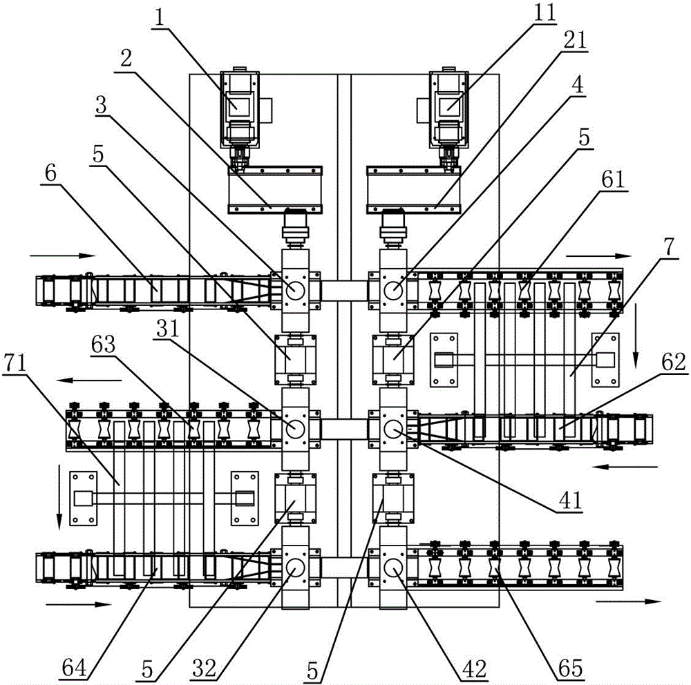
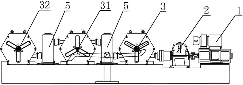
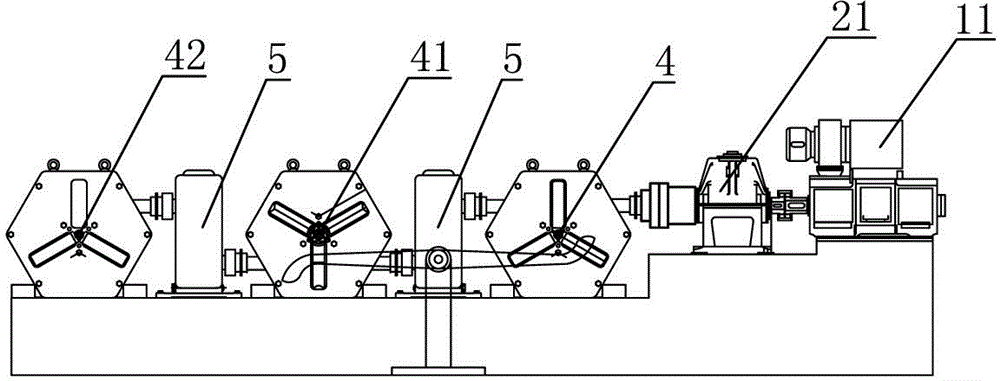
[0015] Such as figure 1 , figure 2 , image 3 As shown, the metal bar rolling production line includes: at least two longitudinally arranged rolling mill rows, each row of rolling mill rows includes at least two horizontal three-roll Y-shaped rolling mills, that is, all rolling mills The row-type three-roller Y-type rolling mills in the row are horizontally arranged into at least two rows of rolling units; each row of rolling mills is driven by a transmission device consisting of an electric motor and a reduction box. In this embodiment, the metal The bar rolling production line includes: two longitudinally arranged rolling mill rows, each row of rolling mill rows is provided with three row-type three-roll Y-shaped rolling mills, that is, the metal bar rolling production line includes six row-type Three-roll Y-rolling mills 3, 31, 32, 4, 41...


PUM


Abstract

The invention discloses a metal bar rolling production line for rolling metal bars. The production line comprises at least two rolling mill columns arranged longitudinally, each rolling mill column comprises at least two transverse three-roll Y-shaped rolling mills, namely the transverse Y-shaped rolling mills in all the rolling mill columns are transversely arranged in at least two rows of rolling mill units; each rolling mill column is driven by a transmission device, and the rotating directions of the two adjacent transverse three-roll Y-shaped rolling mills in each rolling mill column are opposite; a conveying roll table for conveying rolled pieces is arranged at an inlet or an outlet of each transverse three-roll Y-shaped rolling mill in each row of rolling mill unit, the rolling rotating directions of the transverse three-roll Y-shaped rolling mills in each row of rolling mill unit are the same, and the rolling rotating directions of the transverse three-roll Y-shaped rolling mills in two adjacent rows of rolling mill units are opposite. The production line has the advantages of saving occupied area and equipment investment, improving the rolling speed and reducing temperature drop of the rolled pieces, and is high in rolling precision.

Description

technical field [0001] The invention relates to the field of metal bar rolling, in particular to a metal bar rolling production line for rolling metal bars. Background technique [0002] At present, there are mainly two types of production lines for rolling metal bars. One is the three-roller-in-line metal bar rolling production line. The rolling mill has three horizontal rolls set at intervals from top to bottom. The rolling method is to first roll the workpiece - the metal bar between the middle roll and the lower roll in the three-roll mill, and then pass it manually. Move the metal bar between the upper roll and the middle roll in the three-high transverse rolling mill, so that the metal bar is rolled from between the upper roll and the middle roll, and then manually move the metal bar laterally to the next one The three-high transverse rolling mill repeats the above-mentioned rolling process until the finished metal bar is rolled out. The above-mentioned three-roller...

Claims


Application Information

Patent Timeline
Patent Type & Authority Patents(China)
IPC IPC(8): B21B1/18
Inventor 朱艳春郭拉凤秦建平帅美容楚志兵田亚琴
Owner ZHANGJIAGANG CHANGLI MACHINERY
Why Eureka
Try Eureka