Shell manufacturing process with perforation and extrusion processes

A manufacturing process and shell technology, applied in the field of shell manufacturing process, to achieve the effect of reducing production costs

Inactive Publication Date: 2012-10-17
苏州世鼎电子有限公司
View PDF6 Cites 0 Cited by
  • Summary
  • Abstract
  • Description
  • Claims
  • Application Information

AI Technical Summary

Problems solved by technology

[0009] The purpose of the present invention is to overcome the defects existing in the existing shell manufacturing process and provide a new shell manufacturing process with perforation and extrusion procedures. The technical problem to be solved is to develop and desi...

Method used


Image

  • Shell manufacturing process with perforation and extrusion processes
  • Shell manufacturing process with perforation and extrusion processes
  • Shell manufacturing process with perforation and extrusion processes

Examples


Embodiment Construction

[0039] In order to further explain the technical means and effects of the present invention to achieve the intended purpose of the invention, the specific implementation of the shell manufacturing process with perforation and extrusion procedures proposed according to the present invention will be described below in conjunction with the accompanying drawings and preferred embodiments. , processing method, steps, features and effects thereof are described in detail below.

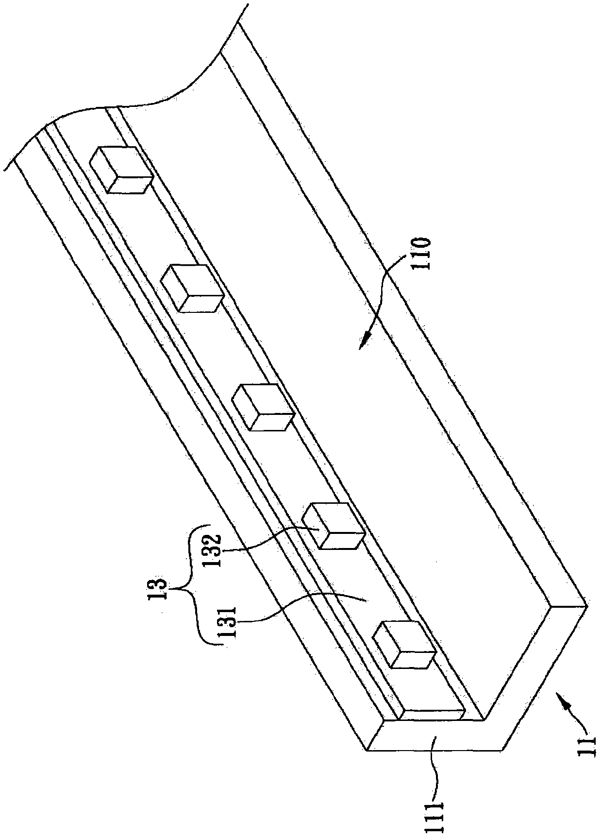
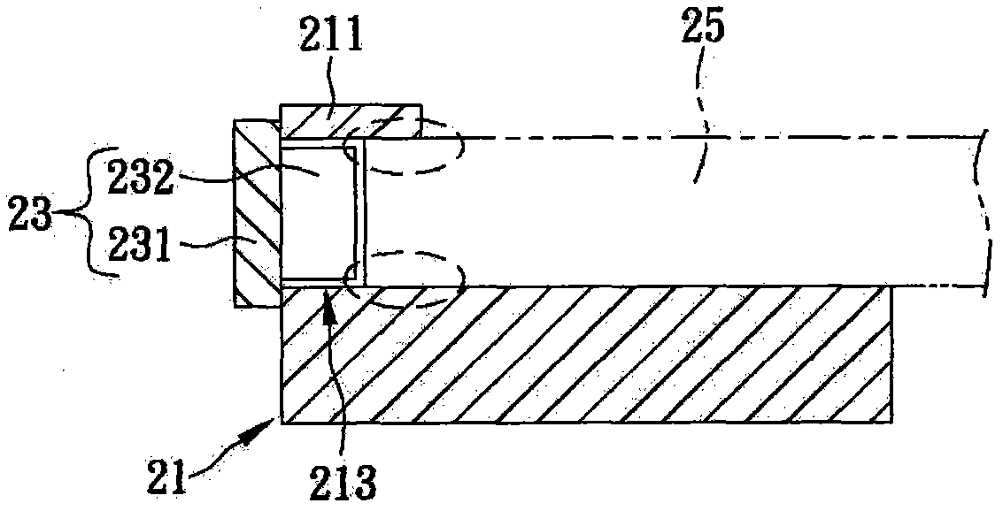
[0040] The present invention is a shell manufacturing process with perforation and extrusion procedures. In the first embodiment of the present invention, please refer to Figure 3A-Figure 3C As shown, the shell manufacturing process is applied to a shell 31 formed by aluminum extrusion or sheet metal, wherein the shell 31 can be used as a carrier for light-emitting elements (such as: light-emitting diodes 413) and light guide plates 43 on a display backlight module , it is particularly mentioned here that t...


PUM


Abstract

The invention discloses a shell manufacturing process with perforation and extrusion processes. The shell serves as a luminous element on a backlight module of a display and a carrier of a light guide plate, and at least two corresponding side edges of the shell are respectively and convexly provided with a supporting wall so as to form an accommodating space between the supporting walls. The shell manufacturing process comprises the following steps of: executing a first perforation process on the supporting walls to form a plurality of perforated holes; executing an extrusion process at a position of the supporting wall surface opposite to the accommodating space to form a groove at a position corresponding to the holes, and reducing the depth of the holes; executing a second perforation process at the position of the holes, so that a light-emitting diode light bar can be fixed to the outer side faces of the supporting walls, and the light-emitting diodes on the light-emitting diode light bar can be accommodated in the corresponding hole. Therefore, compared with the conventional known shell manufacturing process, the shell manufacturing process with the perforation and extrusion processes has the advantages that the required shell can be rapidly and accurately manufactured through a milling process of a milling machine table, and the production cost of a provider is effectively reduced.

Description

technical field [0001] The invention relates to a shell manufacturing process, in particular to a shell manufacturing process through a perforated extrusion process, which can make a plurality of holes on the shell to accommodate light-emitting diodes. Background technique [0002] Compared with CRT (Cathode ray tube, CRT) TVs, Flat Panel Display (FPD) has a thinner overall body and does not take up too much indoor space, which is beneficial to people's planning. The demand for interior design, and the overall light weight, which is convenient for people to move by themselves, has gradually replaced traditional picture tube TVs and has become the first choice for people to buy TVs. Generally speaking, flat-panel TVs can be roughly divided into two types, one is LCD panel (Liquid Crystal Display, referred to as LCD) TV, and the other is plasma panel (Plasma Display Panel, referred to as PDP) TV. , mostly 32 inches to 42 inches, but the size of the plasma panel TV is basicall...

Claims


Application Information

Patent Timeline
IPC IPC(8): B23P15/00
Inventor 陈灿荣
Owner 苏州世鼎电子有限公司
Why Eureka
Try Eureka