Abrasive belt grinding device applicable to inner and outer cambered surfaces of blades of aerospace blisk

A grinding technology for blisks and abrasive belts, which is applied in the direction of abrasive belt grinders, grinding/polishing equipment, grinding machines, etc., can solve the problems of limited space and difficult insertion of grinding heads, so as to ensure the quality of the profile and guarantee Rigidity, the effect of reducing labor intensity

Inactive Publication Date: 2012-10-17
CHONGQING UNIV +1
7 Cites 38 Cited by

AI-Extracted Technical Summary

Problems solved by technology

However, due to the small gap between the blades of the integral blisk, the existing abrasive belt grinder uses the grinding head to con...

Abstract

The invention discloses an abrasive belt grinding device applicable to inner and outer cambered surfaces of blades of aerospace blisk. An X axis transverse feed mechanism, a Y axis transverse feed mechanism and a Z axis longitudinal feed mechanism form a grinding head feed mechanism; an A axis deflection motor, an A axis deflection bracket, a B axis motor, a gear train bracket, a C axis motor, a C axis revolving bracket and the like form a position adjusting mechanism of the grinding head. The abrasive belt grinding device provided by the invention guarantees rigidity of a grinding head mechanism and a work piece clamping mechanism through rational distribution of the grinding head feeding, the position adjustment of the grinding head and the position and angle adjustment of the work piece and through combination of space in six degrees of freedom by a short transmission chain; a contact wheel and an abrasive belt can cut into a narrow gap between two blades of the blisk, so as to ensure the contact between the contact wheel and the work piece to be stable when the contact wheel rotates at a high speed; so that the abrasive belt grinding device can improve the work efficiency, and meanwhile, dimensional accuracy of complex cambered surface of the work piece in processing can be guaranteed, the quality of the molded surface is ensured, the rate of qualified products is improved, the labor intensity of workers is reduced and the management and production costs are lowered.

Application Domain

Belt grinding machines

Technology Topic

Six degrees of freedomBelt grinding +4

Image

  • Abrasive belt grinding device applicable to inner and outer cambered surfaces of blades of aerospace blisk
  • Abrasive belt grinding device applicable to inner and outer cambered surfaces of blades of aerospace blisk
  • Abrasive belt grinding device applicable to inner and outer cambered surfaces of blades of aerospace blisk

Examples

  • Experimental program(1)

Example Embodiment

[0034] The present invention will be further described below in conjunction with the drawings and embodiments:
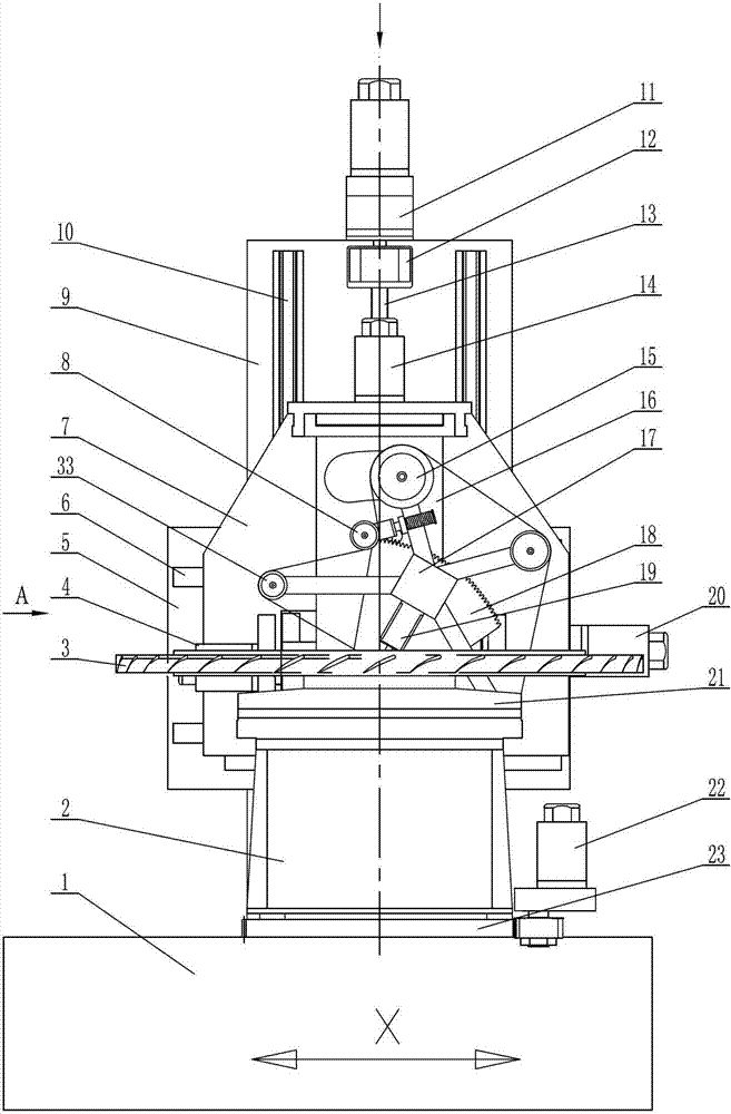
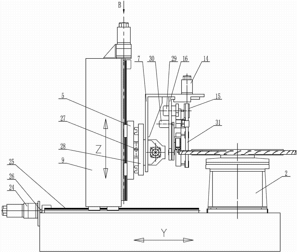
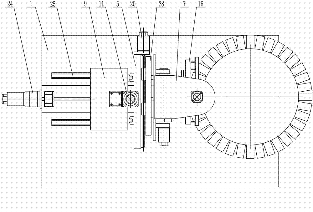
[0035] Such as figure 1 , figure 2 , image 3 As shown, the bed 1 is a rectangular parallelepiped structure, and the bed 1 is like figure 2 The workpiece turntable 2 is set on the top of the right end shown. The bottom of the workpiece turntable 2 is provided with a slewing support body 23. The slewing support body 23 is similar to a bearing structure and has an inner ring and an outer ring that can rotate relatively. The inner ring is fixed on the bed 1, the outer ring of the slewing support body 23 is a gear structure, the outer ring gear of the slewing support body 23 is fixed to the workpiece turntable 2, and the outer ring gear meshes with the gear on the output shaft of the workpiece turntable motor 22 . When the workpiece turntable motor 22 is running, the outer ring gear of the slewing support body 23 can be driven by a gear, so that the outer ring gear of the slewing support body 23 and the workpiece turntable 2 rotate together. A workpiece fixture 21 is installed on the top of the workpiece turntable 2 for clamping the workpiece 3. The structure and working principle of the workpiece holder 21 are all the prior art, and will not be repeated here.
[0036] Such as figure 2 , image 3 As shown, a column 9 is provided on the left side of the workpiece turntable 2. The column 9 has a rectangular parallelepiped structure and is connected to the bed 1 through a Y-axis transverse feed mechanism, and the column 9 is perpendicular to the bed 1. The Y-axis transverse feed mechanism includes a Y-axis motor 24, a Y-axis linear guide 25, a Y-axis screw 26, a Y-axis bearing seat, and a Y-axis screw nut seat. The parallel Y-axis linear guide 25, the Y-axis linear guide 25 is arranged along the length of the bed 1, the column 9 is slidingly matched with the two Y-axis linear guides 25 through the sliding block at the bottom of the column. There is a Y-axis screw 26 parallel to it, and the distance between the Y-axis screw 26 and the two Y-axis linear guides 25 is equal. The Y-axis screw 26 is supported on the bed 1 by a Y-axis bearing seat, and a Y-axis screw nut seat screwed with the Y-axis screw 26 is fixed on the column 9. The left end of the Y-axis screw 26 is connected to the Y-axis motor 24 through a coupling. The Y-axis motor 24 is installed on the left end of the bed 1, and the Y-axis motor 24 is equipped with a reducer.
[0037] Such as figure 1 , figure 2 , image 3 As shown, a sliding plate 5 is installed on the surface of the column 9 facing the workpiece turntable 2. The sliding plate 5 has a rectangular plate structure and is connected to the column 9 through a Z-axis longitudinal feeding mechanism. The Z-axis longitudinal feed mechanism includes a Z-axis motor 11, a coupling 12, a Z-axis screw 13, a Z-axis linear guide 10, a Z-axis bearing seat and a Z-axis screw nut seat, and the column 9 faces the workpiece turntable 2 Two Z-axis linear guides 10 parallel to each other are arranged on the surface of the Z-axis. The Z-axis linear guides 10 are arranged in the up and down direction and are perpendicular to the upper surface of the bed 1. The slide plate 5 slides with the two Z-axis linear guides 10 through the slider. Cooperate. A Z-axis screw rod 13 parallel to the two Z-axis linear guides 10 is provided, and the distance between the Z-axis screw 13 and the two Z-axis linear guides 10 is equal. The Z-axis screw 13 is supported on the column 9 by a Z-axis bearing seat, and a Z-axis screw nut seat matched with the Z-axis screw 13 is fixed on the sliding plate 5. The upper end of the Z-axis screw 13 is connected to the Z-axis motor 11 through a coupling 12, the Z-axis motor 11 is installed on the top of the column 9, and the Z-axis motor 11 is equipped with a reducer.
[0038] Such as figure 1 , figure 2 , image 3 As shown, a grinding head support 28 is installed on the surface of the sliding plate 5 facing the workpiece turntable 2 through an X-axis transverse feed mechanism. The X-axis transverse feed mechanism includes an X-axis motor 20, an X-axis linear guide 6, an X-axis screw 27, an X-axis bearing seat and an X-axis screw nut seat, and is arranged on the surface of the sliding plate 5 facing the workpiece turntable 2. There are two X-axis linear guides 6 parallel to each other. The X-axis linear guides 6 are arranged along the width direction of the bed 1, and the grinding head support 28 is slidingly matched with the two X-axis linear guides 6 through a sliding block. An X-axis screw 27 parallel to the two X-axis linear guides 6 is provided, and the distance between the X-axis screw 27 and the two X-axis linear guides 6 is equal. The X-axis screw 27 is supported on the sliding plate 5 by an X-axis bearing seat, and an X-axis screw nut seat screwed with the X-axis screw 27 is fixed on the grinding head support 28. One end of the X-axis screw 27 is connected to the X-axis motor 20 through a coupling. The X-axis motor 20 is mounted on the sliding plate 5, and the X-axis motor 20 is equipped with a reducer.
[0039] Such as figure 1 , figure 2 , image 3 As shown, a rotary shaft is installed on the end surface of the grinding head support 28 facing the workpiece turntable 2, and the rotary shaft is arranged in the front and rear direction and is parallel to the X-axis screw 27. The A-axis yaw bracket 7 is fixed on the rotating shaft, and the A-axis yaw motor 4 is installed beside the rotating shaft. The A-axis yaw motor 4 is installed on the A-axis yaw bracket 7, and the A-axis yaw motor 4 is passed through the reducer. After deceleration, the output shaft is connected to the rotating shaft through a coupling. A first bevel gear is sleeved on the rotating shaft, and the first bevel gear meshes with the second bevel gear installed on the grinding head support 28. The top of the A-axis yaw bracket 7 deforms and bends toward the workpiece turntable 2 to form a horizontal positioning plate. A C-axis motor 14 is installed on the horizontal positioning plate. The output shaft of the C-axis motor 14 is vertically downward. After the C-axis motor 14 is decelerated by the reducer, it is connected to the C-axis slewing bracket 16, and the C-axis slewing bracket 16 is suspended on the horizontal positioning plate on the top of the A-axis yaw bracket 7.
[0040] Such as figure 1 , figure 2 , Figure 4 As shown, the C-axis slewing bracket 16 is rotatably connected with a gear train bracket 17, which is equipped with a spindle motor 29, and the spindle motor 29 is located in the long arc-shaped through hole on the C-axis slewing bracket 16. To avoid interference. The output shaft of the spindle motor 29 extends horizontally to the right, and a drive wheel 15 is installed on the output shaft of the spindle motor 29. The drive wheel 15 is connected to the supporting wheel 33 and the contact wheel 32 through the sanding belt 31. The supporting wheel 33 is mounted on the wheel. On the tie bracket 17, the number of the supporting wheels 33 is determined according to actual needs, and it can be 1, 2, 3 or more. The supporting wheel 33 and the contact wheel 32 are in the same plane, and both are located in a closed loop surrounded by the abrasive belt 31. The gear train bracket 17 is equipped with a driven gear 18, the driven gear 18 is fan-shaped, and external teeth are provided on the large arc surface of the driven gear 18, and the external teeth are connected to the output shaft of the B-axis motor 30 The driving gear meshes, the B-axis motor 30 is installed on the C-axis rotating support 16, and the B-axis motor 30 is equipped with a reducer. A cylinder 19 is installed on the wheel train bracket 17, the piston rod of the cylinder 19 extends obliquely downward, and the contact wheel 32 is detachably mounted on the piston rod of the cylinder 19. A tensioning wheel 8 is also installed on the gear train bracket 17 through an elastic mechanism, and the tensioning wheel 8 is located outside the closed loop surrounded by the sand belt 31 and is pressed against the sand belt 31.
[0041] The working principle of the present invention is as follows:
[0042] The workpiece 3 is clamped on the workpiece fixture 21, and the workpiece fixture 21 and the workpiece 3 can be driven to rotate by the workpiece turntable motor 22 to adjust the position of the blade on the workpiece 3 to be processed. The contact wheel 32 and the corresponding abrasive belt 31 cut into the narrow gap between the two adjacent blades of the workpiece 3, the spindle motor 29 runs, and the spindle motor 29 drives the abrasive belt 31 through the drive wheel 15 to polish and polish the blades of the workpiece 3 Processing. The position of the contact wheel 32 can be adjusted in six directions, namely:
[0043] The X-axis motor 20 runs and drives the X-axis screw 27 to rotate after deceleration, so that the X-axis screw nut seat and the grinding head support 28 move linearly along the X-axis screw 27, and the grinding head support 28 makes a straight line in the front and back direction. Movement can adjust the position of the contact wheel 32 in the X-axis direction.
[0044] The Y-axis motor 24 runs. After decelerating, the Y-axis screw 26 is driven to rotate, so that the Y-axis screw nut seat and the column 9 move linearly along the Y-axis screw 26, and the column 9 moves linearly in the left and right directions. Adjust the position of the contact wheel 32 in the direction.
[0045] The Z-axis motor 11 runs and drives the Z-axis screw 13 to rotate after deceleration, so that the Z-axis screw nut seat and the sliding plate 5 move linearly along the Z-axis screw 13, and the sliding plate 5 moves up and down in the vertical direction. The position of the contact wheel 32 is adjusted in the axial direction.
[0046] The A-axis yaw motor 4 runs. Because the second bevel gear is fixedly installed on the grinding head support 28, the first bevel gear, the rotating shaft and the A-axis yaw bracket 7 are in a small range under the action of the A-axis yaw motor 4 The inner swing can adjust the position of the contact wheel 32 in the A-axis direction.
[0047] The B-axis motor 30 runs and drives the gear train bracket 17 to rotate through gear transmission, so that the position of the contact wheel 32 can be adjusted in the B-axis direction.
[0048] The operation of the C-axis motor 14 drives the rotation of the C-axis rotating bracket 16 and can adjust the position of the contact wheel 32 in the C-axis direction.

PUM

no PUM

Description & Claims & Application Information

We can also present the details of the Description, Claims and Application information to help users get a comprehensive understanding of the technical details of the patent, such as background art, summary of invention, brief description of drawings, description of embodiments, and other original content. On the other hand, users can also determine the specific scope of protection of the technology through the list of claims; as well as understand the changes in the life cycle of the technology with the presentation of the patent timeline. Login to view more.

Similar technology patents

Automatic device for welding and detecting lithium battery

ActiveCN103904367AShorten the running distanceImprove work efficiency
Owner:DONGGUAN HONBRO LI BATTERY EQUIP TECH

Vacuum cleaner

InactiveCN103356140Aprevent liftingImprove work efficiency
Owner:SUZHOU HAAN TECH +1

Classification and recommendation of technical efficacy words

  • Guaranteed accuracy
  • Improve work efficiency

Cooperation service platform facing different source data

InactiveCN101174957AImprove management level and qualityImprove work efficiency
Owner:NANJING UNIV OF FINANCE & ECONOMICS

Screw drilling tool, vertical drilling tool testing method and well inclination simulation testing equipment

InactiveCN111594144AReduced height requirementsImprove work efficiency
Owner:DEZHOU UNITED GASOLINEEUM MACHINERY

Method for intelligent automatic identification of transmission circuit parts

Owner:INFORMATION COMM COMPANY STATE GRID SHANDONG ELECTRIC POWER +2

Keyboard spill-proofing mechanism

ActiveUS7030330B2minimize manufacturing costimprove work efficiency
Owner:LITE ON SINGAPORE PTE LTD
Why Eureka
Try Eureka