Liquid gas fuel liquid direct-injection device and composite valve of engine

A technology of liquefied gas fuel and engine, applied in the direction of combustion engine, internal combustion piston engine, engine components, etc., to achieve the effects of suppressing surface ignition and deflagration, good inheritance, and improving charging efficiency

Inactive Publication Date: 2012-10-17
潍坊威度电子科技有限公司
View PDF6 Cites 1 Cited by
  • Summary
  • Abstract
  • Description
  • Claims
  • Application Information

AI Technical Summary

Problems solved by technology

[0005] The technical problem to be solved by the present invention is: to provide a liquefied gas fuel liquid direct injection device to solve the technical problem of engine liquefied gas fuel cylinder injection

Method used


Image

  • Liquid gas fuel liquid direct-injection device and composite valve of engine
  • Liquid gas fuel liquid direct-injection device and composite valve of engine
  • Liquid gas fuel liquid direct-injection device and composite valve of engine

Examples


Embodiment 1

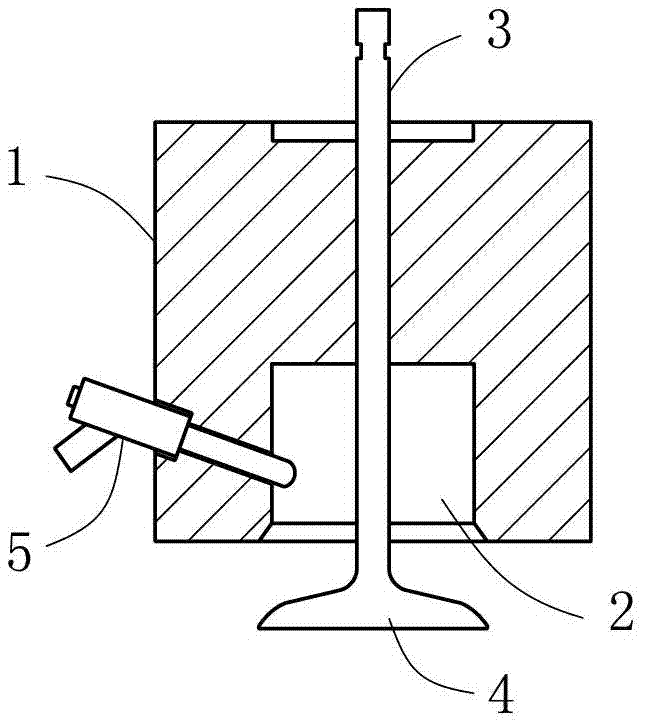
[0019] Such as figure 1 As shown, a liquefied gas fuel liquid direct injection device includes a cylinder head 1 installed on the engine casing, the cylinder head 1 has an isolation chamber 2 with one end open, and the isolation chamber 2 communicates with the combustion chamber of the engine through the open end , the cylinder head 1 is slidably installed with a bacterium valve rod 3 driven by a power unit, usually the power unit is a cam group of an engine gas distribution system or an electric mode, etc., those skilled in the art can use conventional technical means to implement, and will not repeat them here. The end of the bacteria valve rod 3 has a bacteria valve 4 used to seal the open end of the isolation chamber 2; the cylinder head 1 is equipped with an electronically controlled liquid spray valve 5 for measuring the injection amount and injection timing, and the electronically controlled liquid spray valve The shower head of 5 stretches into isolation cavity 2.

[...

Embodiment 2

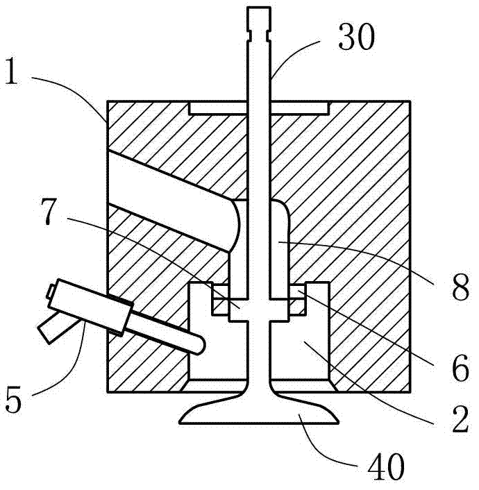
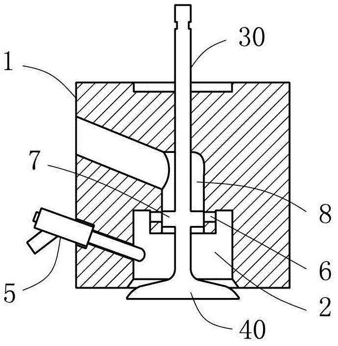
[0023] Such as figure 2 , image 3 and Figure 4 Commonly shown, the main idea is to integrate the liquefied gas fuel liquid direct injection device and the intake valve of the engine into a composite engine valve, including a cylinder head 1 installed on the engine casing, and the cylinder head 1 has an isolation valve with one end open Cavity 2, isolation chamber 2 communicates with the combustion chamber of the engine through the open end, and the valve rod 30 driven by the power device is slidably installed on the cylinder head 1, usually the power device is the engine gas distribution system cam group or electric mode, etc., the technology in the art Personnel can utilize usual technical means to implement, no longer go into details here, the end of valve stem 3 has a valve bacteria valve 40 for sealing the open end of isolation chamber 2; Air intake channel 8, the end of the intake channel 8 is provided with a radial through hole 6 communicating with the isolation cha...


PUM


Abstract

The invention discloses a liquid gas fuel liquid direct-injection device, and belongs to the technical field of engines. The liquid gas fuel liquid direct-injection device comprises a cylinder head arranged on a shell of an engine, the cylinder head is provided with an isolating cavity with an opened end, the isolating cavity is communicated with a combustion chamber of the engine through the opened end, a poppet valve stem which is driven by a power device is slidably arranged on the cylinder head, and a pneumatic poppet valve which is used for sealing the opened end of the isolating cavity is arranged at an end of the poppet valve stem; and an electric control liquid spraying valve is arranged on the cylinder head, and a sprayer of the electric control liquid spraying valve extends in the isolating valve. The invention also discloses a composite valve of an engine, the liquid gas fuel liquid direct-injection device and a gas inlet door of the engine are integrated, and multiple effects of controlling air and gas fuel to be injected into a cylinder of the traditional engine structure are kept. Liquid gas fuel is injected to the inside of the cylinder of the engine, and the liquid gas fuel liquid direct-injection device and the composite valve of the engine are widely applied to engines.

Description

technical field [0001] The invention relates to the technical field of engines, in particular to a liquefied gas fuel liquid direct injection device and an engine composite valve. Background technique [0002] Compared with gaseous gaseous fuels, liquid gaseous fuels have higher energy storage density and stronger engine endurance. For example, after natural gas is purified, it becomes LNG (liquefied natural gas) at -162°C, and its volume is 1 / 625 of the standard condition. At present, the engine uses liquid gas fuel, which is generally heated and vaporized first, and then the gas fuel gas channel is injected to form a supply subsystem. One of the disadvantages of this method is that the gasification link requires heat balance management, which requires a huge auxiliary system; secondly, the engine charging efficiency is low and the power is reduced. [0003] Gas fuel in-cylinder injection has many advantages: it can strengthen the control of the combustion process through...

Claims


Application Information

Patent Timeline
Patent Type & Authority Applications(China)
IPC IPC(8): F02M21/02F02F1/24
CPCY02T10/32Y02T10/30
Inventor 孙军李澎陈洪海王秀强
Owner 潍坊威度电子科技有限公司
Why Eureka
Try Eureka