Dustproof and waterproof structure of ventilator

A dustproof, waterproof, and ventilator technology, which is applied to mechanical equipment, machines/engines, liquid fuel engines, etc., can solve problems affecting heat dissipation capacity, rotor dynamic balance damage, radiator dirty, etc., to improve rotor stability, Strong anti-fouling ability, prolonging the effect of cleaning time and maintenance cycle

Inactive Publication Date: 2012-10-17
CRRC DALIAN INST CO LTD
View PDF6 Cites 2 Cited by
  • Summary
  • Abstract
  • Description
  • Claims
  • Application Information

AI Technical Summary

Problems solved by technology

Coal ash, dust, etc. are easy to deposit on the blades of the fan, causing damage to the dynamic balance of the rotor
When rain and snow can enter the inside of the fan, if the protection is not proper, it may enter the inside of the motor bearing and cause bearing damage
However, in actual use, the existing ventilators often have faults such as large vibration and bearing burnout.
And all kinds of pollutants are directly blown to the radiator of the main converter and the radiator of the main transformer below with the cooling air through the fan, which will easily cause the radiator to be dirty and seriously affect the heat dissipation capacity.

Method used


Image

  • Dustproof and waterproof structure of ventilator

Examples


Embodiment Construction

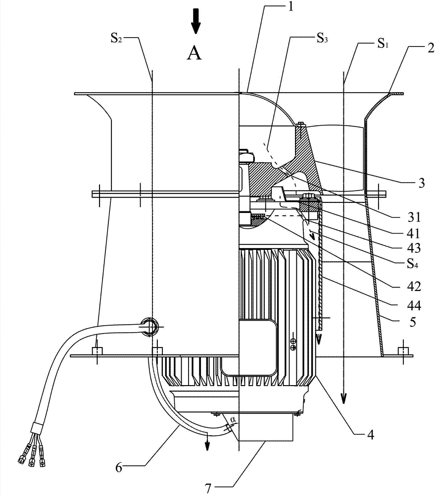
[0016] like figure 1 As shown, a dust-proof and waterproof structure for a ventilator includes a shroud 1, an upper air cylinder 2, an impeller 3, a motor 4, a diffusion cylinder 5, a cable 6, and a junction box 7, and the impeller 3 is a radial acceleration impeller, The inlet of the impeller 3 is provided with the shroud 1, and the connecting arm between the outer connecting part of the hub and the inner connecting part of the hub is provided with a drain hole I31, and the drain hole I31 is from the inside of the hub. The connecting part is a through hole opened in the inclined direction of the outer connecting part of the hub, and the sewage hole I31 can discharge impurities such as rain, snow and water (hereinafter referred to as sewage) entering the hub of the impeller 3; the main shaft of the motor 4 and the impeller 3-axis connection, the main shaft of the motor 4 is provided with a labyrinth dustproof ring 42 at a position close to the inlet of the motor 4, and the lab...


PUM


Abstract

The invention discloses a dustproof and waterproof structure of a ventilator, which comprises a flow guide cover, an upper wind tube, an impeller, a motor, a diffusion tube, a cable and a junction box and is characterized in that the flow guide cover is arranged at an inlet of the impeller; a dirt discharge hole I is arranged in a connecting arm between a hub external connecting part and a hub internal connecting part of the impeller; the main shaft of the motor is in shaft connection with the impeller; a dustproof cover is arranged on the outer edge of a motor cover at one side of the motor connected with the impeller; a dirt discharge hole II is arranged in the outer edge of the motor cover; an inner tube of the diffusion tube is sleeved and fixedly arranged at the outer side of the motor; a rear guide blade is fixedly arranged between the inner tube of the diffusion tube and the diffusion tube; a gap is formed between the inner wall of the inner tube of the diffusion tube and the outer edge of the motor cover; the upper wind tube is sleeved on the outer side of the impeller and is fixedly connected with the diffusion tube; the junction box is fixedly arranged at the lower end of the motor; and the cable passes through the diffusion tube and is connected with the junction box. The dustproof and waterproof structure of the ventilator has stronger stain resistance and strong rotor stability, and the cleaning time and the maintenance period of a rotor can be prolonged.

Description

technical field [0001] The invention relates to a ventilator, in particular to a dustproof and waterproof structure for the ventilator. Background technique [0002] At present, fans are mainly used to cool traction converters and main transformers. The electric locomotives used in the western region mainly transport coal. In actual work, the ventilator will suck directly from the top of the locomotive without filtering. This may allow dust, grease, rain, snow, etc. to enter. Coal ash, dust, etc. are easily deposited on the blades of the fan, causing damage to the dynamic balance of the rotor. When rain and snow can enter the inside of the fan, if the protection is not proper, it may enter the inside of the motor bearing and cause bearing damage. However, in actual use, the existing fans often experience large vibration and bearing burnout failures. Various pollutants are directly blown to the main converter radiator and main transformer radiator below through the fan t...

Claims


Application Information

Patent Timeline
IPC IPC(8): F04D29/28F04D29/08F04D29/70F04D29/00F04D25/08
Inventor 李瑜幺克东
Owner CRRC DALIAN INST CO LTD
Why Eureka
Try Eureka