Quickly dismounted milling cutter clamp

A milling cutter fixture and quick-release technology, which is applied to milling cutters, clamping, milling machine equipment, etc., can solve the problems of easy loosening and low tool clamping efficiency, and achieve convenient adjustment, fast clamping and dismounting speed, and improved The effect of stability

Inactive Publication Date: 2015-05-20
SUZHOU LU LU SHUN ELECTRICAL EQUIP
View PDF7 Cites 0 Cited by
  • Summary
  • Abstract
  • Description
  • Claims
  • Application Information

AI Technical Summary

Problems solved by technology

[0006] The technical problem to be solved by the present invention is: to overcome the technical problem of low tool clamping efficiency and easy loosening in the prior art, and to provide a quick-release milling tool that can quickly and stably clamp the tool. Tool holder

Method used


Image

  • Quickly dismounted milling cutter clamp

Examples


Embodiment Construction

[0031] The present invention is described in further detail now in conjunction with accompanying drawing. These drawings are all simplified schematic diagrams, which only illustrate the basic structure of the present invention in a schematic manner, so they only show the configurations related to the present invention.

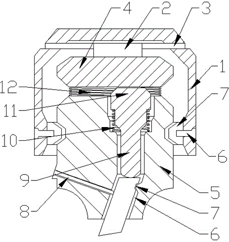
[0032] Such as figure 1 As shown, the present invention is a quick-release milling tool holder, including a rotating head 1 and a tool holder 5. The rotating head 1 includes a cylindrical cavity, and the cylindrical cavity of the rotating head 1 is sleeved on the The upper part of the tool holder 5;

[0033] The tool chuck 5 includes a chuck body, and a cylindrical cavity is arranged in the chuck body, and the cylindrical cavity includes a vertical section and an inclined section, and the inclined section includes an upper end wall surface oppositely arranged and the lower end wall surface, a bar-shaped block is arranged on the lower wall surface, and the bl...


PUM


Abstract

The invention relates to a quickly dismounted milling cutter clamp which comprises a rotary head and a tool chuck. The rotary head comprises a columnar cavity, and the columnar cavity of the rotary head is connected to the upper portion of the tool chuck in a sleeving mode. The tool chuck comprises a chuck body, a columnar cavity is formed in the chuck body, and comprises a vertical segment and an inclined segment, the inclined segment comprises an upper-end wall face and a lower-end wall face opposite to the upper-end wall face, and a strip-shaped clamping block is arranged on the lower-end wall face. A push rod is arranged in the vertical segment of the columnar cavity. A movable cavity is formed between the rotary head and the upper portion of the tool chuck, a cam block is arranged in the movable cavity, the two axial ends of the cam block are rotatably connected with the inner wall of the rotary head, a push portion of the push rod further comprises a push block stretching out of the columnar cavity, the cam block is in contact with the push block, and the cam block is rotated to drive the push rod to move axially.

Description

technical field [0001] The invention relates to a quick-detachable milling cutter clamp, which belongs to the field of tool clamps for machine tools. Background technique [0002] A turning tool is a tool with a cutting part used for cutting. The turning tool is one of the most widely used tools in cutting. The working part of the turning tool is the part that generates and processes the cutting, including the cutting edge, breaking the chips Structural elements such as the structure of rolling or rolling, the space for chip removal or chip storage, and the passage of cutting fluid. The type of the front of the turning tool is mainly determined by the nature of the workpiece material and tool material. The simplest is the plane type, the plane type with positive rake angle is suitable for high-speed steel turning tools and hard alloy turning tools for finishing, and the plane type with negative rake angle is suitable for machining high-strength steel and rough cutting steel...

Claims


Application Information

Patent Timeline
Patent Type & Authority Applications(China)
IPC IPC(8): B23Q3/12B23C5/26
CPCB23Q3/12B23C5/26
Inventor 郭丽娟
Owner SUZHOU LU LU SHUN ELECTRICAL EQUIP
Why Eureka
Try Eureka