Supercharge Your Innovation With Domain-Expert AI Agents!

Process pump for petrochemical industry

A technology for petrochemical and process pumps, which is applied to pumps, pump components, and parts of pumping devices for elastic fluids. The effect of prolonging service life, avoiding failure and improving pumping efficiency

Active Publication Date: 2014-05-07
江苏金鹰流体机械有限公司
View PDF6 Cites 0 Cited by
  • Summary
  • Abstract
  • Description
  • Claims
  • Application Information

AI Technical Summary

Problems solved by technology

Traditional petrochemical pumps have high requirements on the pressure, temperature, viscosity, solid particle content, and corrosiveness of the conveying medium, which cannot be used not only for high-temperature media, but also for high-pressure, high-viscosity, and media containing solid particles. The scope of application of chemical pumps is small
[0003] For the medium containing solid particles, the traditional method is to introduce fluid from the pump outlet into the sealing chamber, and at the same time install a hydrocyclone in the introduction pipeline, and use the filtered medium to flush the sealing chamber. Although this solution can achieve flushing purpose, but the wear on the impeller and pump cover is serious, which affects the service life of the pump

Method used


Image

  • Process pump for petrochemical industry
  • Process pump for petrochemical industry
  • Process pump for petrochemical industry

Examples


Embodiment 1

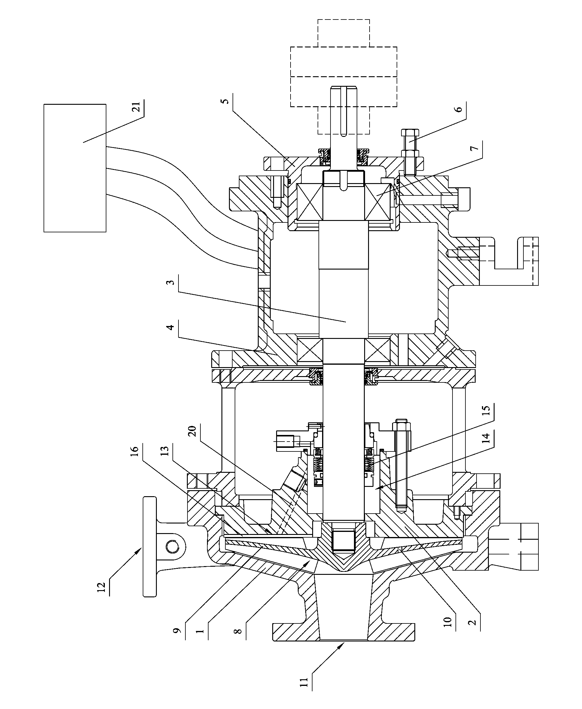
[0024] Embodiment one: see attached figure 1 shown.

[0025] A petrochemical process pump, comprising a pump casing 1, a pump cover 2 connected to the pump casing 1, a pump shaft 3 arranged in the pump casing 1, a bearing housing 4 connected to the pump cover 2, and a pump shaft 3 arranged in the bearing casing 4 The bearing housing 5 that slides in the axial direction of the pump shaft 3. An adjusting screw 6 is arranged between the bearing housing 4 and the bearing seat 5 , a bearing 7 is arranged in the bearing seat 5 , and the pump shaft 3 is arranged in the bearing 7 and its axial direction extends toward the pump cover 2 . The bearing seat 5 can drive the pump shaft 3 and the impeller 9 to move along the axial direction of the pump shaft 3 , thereby effectively controlling the gap between the impeller 9 and the pump casing 1 . In order to monitor and control the operating conditions of the pump in a timely and effective manner, one or more of a liquid level indicator, ...


PUM


Abstract

The invention relates to a process pump for petrochemical industry. The process pump comprises a pump shell, a pump cover and a pump shaft; an impeller cavity is formed between the pump shell and the pump cover; an impeller which is connected to one end of the pump shaft and can be driven by the pump shaft to be rotated is arranged in the impeller cavity; the impeller is provided with a balance hole; the pump shell is provided with a pump inlet and a pump outlet; the surface of the inner wall of the impeller cavity formed by the pump cover is a flow guide surface; a sealing cavity is formed between the pump cover and the pump shaft; a mechanical sealing device is arranged in the sealing cavity; the flow guide surface is provided with a plurality of flow guide ribs which are radial from the center of the flow guide surface to the outer circumference; and when the pump shaft drives the impeller to rotate, a low pressure area is formed on a back pressure side of each flow guide rib, and a through hole which is communicated to the sealing cavity from the impeller cavity is formed in the low pressure area. The process pump has the combined structure of the flow guide ribs and the through hole, so that solid particles flowing in the sealing cavity and heat produced by friction of the mechanical sealing device can be carried away timely, the circulating cooling cleaning of a pump body can be realized, and the failure of the mechanical sealing device can be effectively avoided.

Description

technical field [0001] The invention relates to a petrochemical process pump. Background technique [0002] Petrochemical pumps are the most used rotating equipment in petrochemical production equipment, and also the equipment that consumes the most energy. The electricity consumption accounts for about 50% of the electricity consumption of the whole plant. The pressure of the medium conveyed by the petrochemical pump ranges from back pressure to 300MPa, and the temperature ranges from minus 140°C to nearly 500°C. Some of the medium are viscous, some contain solid particles, and most of them are corrosive. Therefore, finding a way to eliminate the influence of medium pressure, temperature, viscosity, solid content, corrosion, etc. on the pump is the key to ensuring the safe and stable operation of the pump and mechanical seal. Traditional petrochemical pumps have high requirements on the pressure, temperature, viscosity, solid particle content, and corrosiveness of the conv...

Claims


Application Information

Patent Timeline
Patent Type & Authority Patents(China)
IPC IPC(8): F04D29/44
Inventor 房硕君瞿国平
Owner 江苏金鹰流体机械有限公司
Features
  • R&D
  • Intellectual Property
  • Life Sciences
  • Materials
  • Tech Scout
  • Unparalleled Data Quality
  • Higher Quality Content
  • 60% Fewer Hallucinations
Learn More