Shape tube for district heating heat pipe and the method thereof

A central heating and manufacturing method technology, applied in heating methods, household heating, heating systems, etc., can solve problems such as loss of original functions, unstable structure, and damaged pipes, and achieve the effect of preventing deformation

Active Publication Date: 2012-10-17
KOREA DISTRICT HEATING CORP
View PDF5 Cites 6 Cited by
  • Summary
  • Abstract
  • Description
  • Claims
  • Application Information

AI Technical Summary

Problems solved by technology

[0011] However, after a period of time, the telescopic buffer material will be compressed and deformed due to thermal expansion force and ground reaction force, and lose its original function, resulting in problems such as shortened service life of the heat exhaus

Method used


Image

  • Shape tube for district heating heat pipe and the method thereof
  • Shape tube for district heating heat pipe and the method thereof
  • Shape tube for district heating heat pipe and the method thereof

Examples


Example Embodiment

[0040] The special-shaped pipe for central heating heat exhaust pipe with shear stress control ring of the present invention will be described in detail below with reference to the accompanying drawings.

[0041] In the following description, in order to avoid confusing the technical idea of ​​the present invention, detailed descriptions of well-known related functions or structures will be omitted. In addition, the terms used below are defined on the basis of the functions of the present invention, and may vary depending on users' intentions or habits. Therefore, its definition should be understood on the basis of the entire content of this specification.

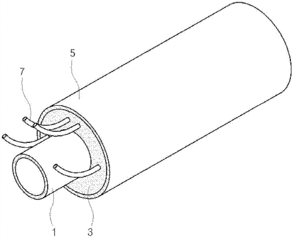
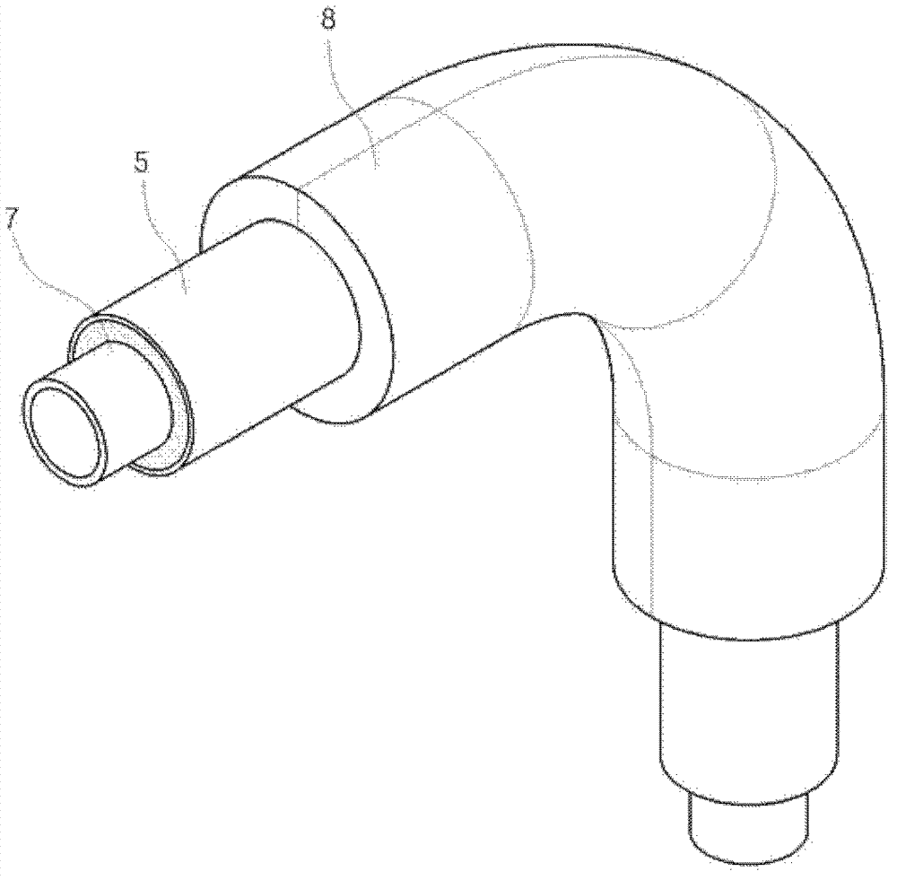
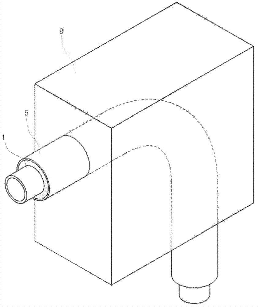
[0042] image 3 It is a structural schematic diagram of the special-shaped pipe for central heating heat exhaust pipe with a shear stress control ring of the present invention, Figure 4 Yes image 3 sectional view of Figure 5a and Figure 5b It is a side view of the structure of the inner tube in the special-shaped ...


PUM


Abstract

The present invention relates to a shape tube for district heating heat pipe having shear control ring and a method thereof. Especially the shape tube comprising: an internal pipe, bent with constant curvature, of which the both ends connected with the district heating heat pipe and flowing medium-temperature hot water inside the internal pipe; an external pipe forming a space and inserting the internal pipe inside, having large diameter than that of the internal pipe; a heat insulator foamed in the space between the internal pipe and the external pipe; and a shear control ring combined to the curves of the internal pipe. According to the present invention as above, the present invention enables to prevent transform in heat pipes in advance by installing shear control rings in the curves of internal pipe of heat pipes bent with constant curvature, and disperse shear stress delivered to the heat insulator.

Description

technical field [0001] The present invention relates to the special-shaped pipe for central heating heat exhaust pipe with a shear stress control ring. The shear stress control ring (SCR, Shear Control Ring) of the shear stress of the insulation material. Background technique [0002] Central heating systems were first developed in Europe in the 1920s to alleviate air pollution caused by the surge in urban population and to save energy. [0003] The heat pipe refers to the heat transfer facility set up for the purpose of central heating, which can supply the heat generated by the central heating facility to the user's mechanical room. [0004] As for the materials of heat pipes for central heating, in the early 1920s when the central heating system was developed, reinforced concrete pipes were mainly used, so the insulation effect was poor and lacked practicality. In the 1960s, the factory-made insulation pipe was successfully developed, which made the central heating syst...

Claims


Application Information

Patent Timeline
IPC IPC(8): F16L59/14F24D19/00
CPCF16L2201/30F16L59/22Y02E20/14F16L9/18F16L43/02F16L59/10F24D10/00
Inventor 李勋林钟元高贤溢赵钟斗金周勇
Owner KOREA DISTRICT HEATING CORP
Why Eureka
Try Eureka