Side intake air microwave drying apparatus

A microwave drying and side-inlet technology, applied in the field of side-inlet microwave drying equipment, can solve the problems of increased energy consumption, serious pollution, and non-environmental protection, and achieve the effects of avoiding ignition, convenient operation, and simple installation

Inactive Publication Date: 2012-10-17
HENAN BODA MICROWAVE EQUIP
View PDF7 Cites 19 Cited by
  • Summary
  • Abstract
  • Description
  • Claims
  • Application Information

AI Technical Summary

Problems solved by technology

Although the cost of burning coal and charcoal is low, it is not environmentally friendly and pollu...

Method used


Image

  • Side intake air microwave drying apparatus
  • Side intake air microwave drying apparatus
  • Side intake air microwave drying apparatus

Examples


Embodiment 1

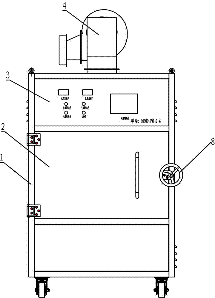
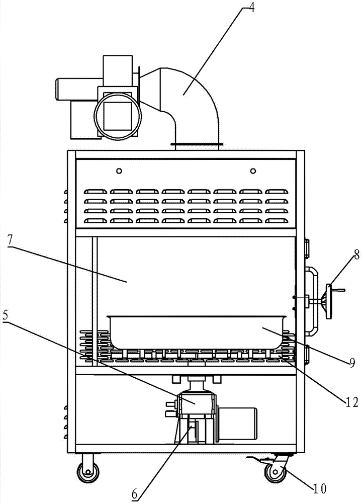
[0019] Embodiment one: see Figure 1 ~ Figure 3 , the side air inlet microwave drying equipment of the present invention adopts a box-type structure, and the middle part of the box body 1 is a microwave action cavity 7, and one side of the microwave action cavity 7 is provided with a door body 2, and the microwave generation source ( Magnetron) and the microwave action cavity are distributed and arranged on the upper part of the box body, and a material tray 9 and a tray support frame 12 are arranged in the microwave action cavity; a power system 5 is installed at the bottom of the microwave action cavity in the box, so that The motor of the above-mentioned power system is connected to the tray support frame through the reduction mechanism, and the material tray is driven to rotate through the rotation of the tray support frame. A certain number of air inlet holes are provided on the side wall of the microwave action cavity, and the top of the box body 1 communicates with the m...

Embodiment 2

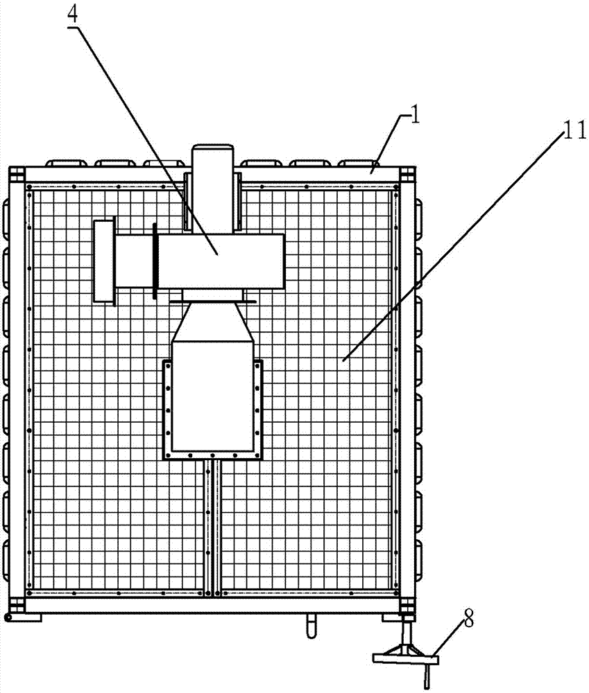
[0021] Embodiment two: see Figure 1 to Figure 4 In this embodiment, the side air inlet microwave drying equipment is different from Embodiment 1 in that the dehumidification system 4 includes air inlets, air ducts, fans and air outlets on the sides of a box-type structure, and the air outlet adopts a top conical structure. The bottom of the big and small head of the air outlet of the fan is a horizontal structure.

[0022] Appropriate holes are opened on the side wall of the cavity to form an air circulation system with the air duct and fan on the top of the cavity, allowing dry air to flow in and moisture to be discharged at the same time. The lower part of the head is horizontal to prevent condensed water from pouring back and affect the dehumidification effect. The dehumidification air duct is easy to disassemble and clean regularly.

Embodiment 3

[0023] Embodiment three: see Figure 1 to Figure 4 , the side air inlet microwave drying equipment of this embodiment is different from Embodiment 1 or Embodiment 2 in that: the material tray 9 is separated from the support frame by a support plate, and anti-flow is provided around the door body 2 of the microwave action cavity. Groove structure, which is equipped with a door seal made of microwave-absorbing material; the upper box of the microwave action cavity is provided with a protective top net 11.

[0024] The door body of the equipment is the import and export of materials, and it is also an important part of the action chamber of microwave equipment, and its function is to prevent microwave leakage. The equipment door is composed of stainless steel frame and stainless steel plate. In order to prevent the microwave from leaking from the gap between the door and the cavity after the door of the microwave equipment is closed, anti-flow groove structures are installed aro...


PUM


Abstract

The invention relates to an industrial microwave application apparatus, and particularly relates to a side intake air microwave drying apparatus. According to the side intake air microwave drying apparatus the middle part of a box type structure acts as a microwave action cavity which is provided with a door body on one side, a microwave resource and the microwave action cavity are matched and separately distributed on the upper part of the box body; the microwave action cavity is provided with a tray and a tray holder; a power system is arranged on the lower part of the microwave action cavity in the box body, a motor of the power system is connected with the tray holder by a reducing mechanism in order to drive the tray to rotate by the tray holder; the side wall of the microwave action cavity is provided with an amount of air intake holes; and the top end of the box body is provided with a moisture pumping system which is communicated with the microwave action cavity. With the adoption of the independent box type structure, the side intake air microwave drying apparatus has the advantages of reasonable design, convenience for operation, easiness of installation, no special requirement to site and materials, and convenience for implementation and promotion.

Description

technical field [0001] The invention relates to an industrial microwave energy application equipment, in particular to a side air inlet microwave drying equipment. Background technique [0002] Microwave drying equipment has obvious energy-saving benefits in the conversion of electrical energy into thermal energy systems. Traditional heating sources use coal, natural gas, oil, and charcoal. Due to the continuous rise in the price of energy materials in recent years, the heating cost of oil and natural gas has increased greatly. Although the cost of burning coal and charcoal is low, it is not environmentally friendly and pollutes seriously. All of the above heating methods require a preheating time, which increases energy consumption. [0003] The biggest feature of industrial microwave drying equipment is "energy saving, environmental protection, and high efficiency", which can increase the conversion rate of electric energy to 72%-78%. And because the industrial microwa...

Claims


Application Information

Patent Timeline
IPC IPC(8): F26B11/18F26B25/00G05D27/02H01F27/12
Inventor 苏建勇张佩利
Owner HENAN BODA MICROWAVE EQUIP
Why Eureka
Try Eureka